
Stepping angle compensation method for stepping motor

A technology of stepping motor and compensation method, which is applied in the direction of motor generator control, electrical components, control system, etc., and can solve the problems of uneven micro-step angle, inflexible control mode, and deviation of air gap magnetic field from expectations, etc.

Inactive Publication Date: 2011-08-17
PLA SECOND ARTILLERY ENGINEERING UNIVERSITY
View PDF5 Cites 7 Cited by
  • Summary
  • Abstract
  • Description
  • Claims
  • Application Information

AI Technical Summary

Problems solved by technology

[0002] No matter what type of stepper motor subdivision driver, in order to achieve the purpose of subdivision, the final output current must be changed according to a certain rule. This rule is the "subdivision function". The existence of factors such as core materials and boundary conditions will cause the air gap magnetic field to deviate from the expected situation. Moreover, due to the existence of a certain friction torque due to the fixed, installed, and connected parts such as motor bearings, the misalignment angle of the motor will change accordingly, resulting in micro-stepping The angle is not uniform, so it is necessary to optimize the winding current value, design an optimization model, and compensate the subdivision function, otherwise, in the open-loop control, the unevenness of the micro-step angle will greatly reduce the linear positioning of the open-loop system precision
[0003] In the prior art before the present invention, because the control method is not flexible enough, it is difficult to compensate the subdivision function on the hardware, so many documents only mention that the subdivision function needs to be compensated, but there is no specific high Accuracy compensation can reach the advent of the method of approaching infinite subdivision that the present invention can achieve

Method used


Image

  • Stepping angle compensation method for stepping motor
  • Stepping angle compensation method for stepping motor
  • Stepping angle compensation method for stepping motor

Examples


Embodiment

[0039] Step 1: Set the subdivision number and step angle of the subdivision driver:

[0040] The present invention sets the step angle as 200" according to the subdivision number and the step angle formula, and each microstep is 2", and one step is essentially the result of accumulating 100 microsteps.

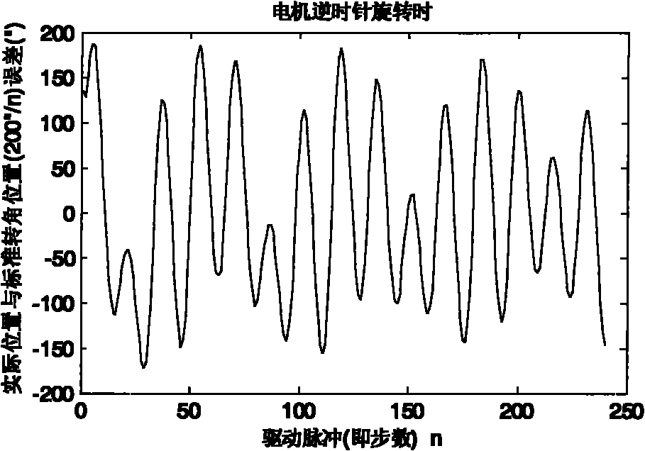
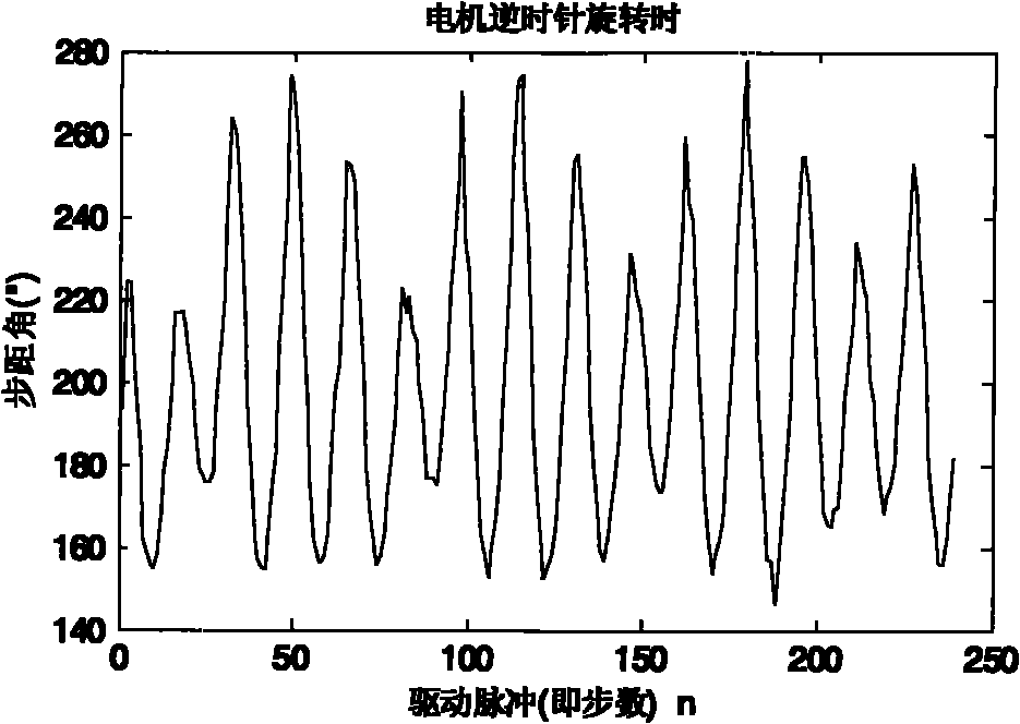
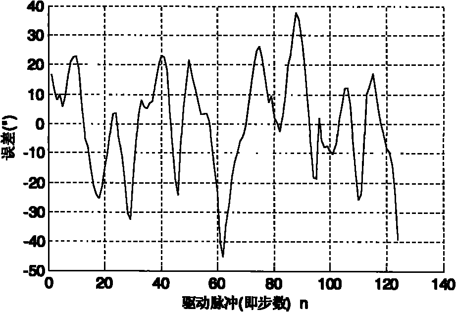
[0041] Step 2: Measure the position error δ with a measurement system that is an order of magnitude more accurate than the stepper motor step angle n : According to the measurement results, the step angle error error model δ(n) is established, and the subdivision compensation function is obtained, and the Fourier analysis is carried out on the relationship between the actual position and the ideal position deviation, and the obtained frequency spectrum is as follows image 3 As shown, there are mainly four peaks in the figure, and the corresponding frequencies are 2, 4, 6, and 8, that is, there are strong signals at these four frequencies, while there is no obvious signal info...


PUM


Abstract

The invention relates to a stepping angle compensation method for a stepping motor. The method is characterized by comprising the following steps of: setting a subdivision number of a subdivision driver and a stepping angle; measuring variations of the stepping angle by using a measurement system with accuracy which is an order of magnitude higher than that of the stepping angle of the stepping motor; and establishing a stepping angle error model according to measurement results, and performing microstep regulation to compensate a stepping angle error to accurately control the rotating position of the stepping motor. Compared with the prior art, the invention can ensure the continuous variation of the subdivision number of the stepping motor, infinite subdivision, stepless speed regulation and the subdivision times of 17,179,869,184 of the stepping motor, flexibly compensate the stepping angle of the stepping motor, make more uniform the stepping angle and make more flexible the control and driving ways; and actual measurement results obtained before and after the compensation show that remarkable effects can be achieved by adopting 'microstep regulation and virtual compensation' for the correction of the stepping angle.

Description

technical field [0001] The invention belongs to the technical field of stepping motor drive circuits, and relates to a stepping motor step angle compensation method. Background technique [0002] No matter what type of stepper motor subdivision driver, in order to achieve the purpose of subdivision, the final output current must be changed according to a certain rule. This rule is the "subdivision function". The existence of factors such as core materials and boundary conditions will cause the air gap magnetic field to deviate from the expected situation. Moreover, due to the existence of a certain friction torque due to the fixed, installed, and connected parts such as motor bearings, the misalignment angle of the motor will change accordingly, resulting in micro-stepping The angle is not uniform, so it is necessary to optimize the winding current value, design an optimization model, and compensate the subdivision function, otherwise, in the open-loop control, the unevennes...

Claims


Application Information

Patent Timeline
IPC IPC(8): H02P8/22
Inventor 谭立龙张志利仲启媛
Owner PLA SECOND ARTILLERY ENGINEERING UNIVERSITY
Learn More