DC solid-state relay

A solid-state relay and resistor technology, applied in electrical components, electronic switches, pulse technology, etc., can solve the problems of inaccurate action, high component reliability requirements, complex solid-state relay control circuit, etc., and achieve the speed of opening and closing Fast, satisfying high-speed effect

Inactive Publication Date: 2011-08-17
HOHAI UNIV
View PDF2 Cites 5 Cited by
  • Summary
  • Abstract
  • Description
  • Claims
  • Application Information

AI Technical Summary

Problems solved by technology

However, the control circuit of solid-state relays is relatively complex and requires high reliability of components, so the application of solid-state relays is also subject to certain restrictions.
It can be foreseen that solid state relays will develop in the direction of small and thin, and modern equipment puts forward higher requirements for the action speed of solid state relays. In addition, the critical voltages of the existing solid state relays are approximately the same when they are turned on and off. It is often impossible to operate accurately near the critical voltage, and critical jitter is prone to occur, which requires a certain adjustment margin between the on-voltage and cut-off voltage of the relay

Method used


Image

  • DC solid-state relay
  • DC solid-state relay
  • DC solid-state relay

Examples


Embodiment Construction

[0015] The circuit connection structure and working principle of the present invention will be described in detail below in conjunction with the accompanying drawings.

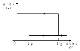
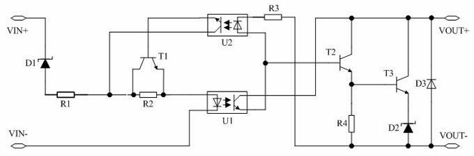
[0016] Such as figure 1 As shown, the present invention provides a DC solid state relay, including an input circuit, an isolation circuit and an output circuit; wherein, the input circuit includes a first resistor R1, a second resistor R2, a first switch tube T1 and a first diode D1, The cathode of the first switching tube T1 is used as the VIN+ terminal of the relay, the anode is connected to one end of the first resistor R1, and the other end of the first resistor R1 is connected to one end of the second resistor R2, and the other end of the first resistor R1 is also connected to the first The collector of the switching tube T1, and the other end of the second resistor R2 is connected to the emitter of the first switching tube T1.

[0017] The isolation circuit includes a first optocoupler U1 and a second o...


PUM


Abstract

The invention discloses a DC solid-state relay, which comprises an input circuit, an isolating circuit and an output circuit. The input circuit comprises a first resistor, a second resistor, a first switching tube and a first diode, wherein the anode of the first switching tube is connected with one end of the second resistor by the first resistor, and the other end of the second resistor is connected with the emitter of the first switching tube. The isolating circuit comprises a first optical coupler and a second optical coupler, wherein the positive input end of the first optical coupler isconnected with the emitter of the first switching tube; the positive and negative output ends of the second optical coupler are connected with the collector and base of the first switching tube respectively; and the positive input end of the second optical coupler is connected with the negative output end of the first optical coupler. The output circuit comprises a third resistor, a fourth resistor, a second switching tube, a third switching tube, a second diode and a third diode, wherein the negative input end of the second optical coupler is connected with the third resistor; the positive input end of the second optical coupler is connected with the base of the second switching tube; and the collector of the second switching tube is connected with the positive output end of the first optical coupler. The relay has operating value or return value parameters which can be adjusted in a relatively wider range, and meets the requirement of high speed.

Description

technical field [0001] The invention belongs to the field of relays, and relates to a solid-state relay, in particular to a high-speed small DC solid-state relay structure with low loss, long service life and adjustable operating value or return value parameters. Background technique [0002] Solid state relay is a kind of non-contact electronic switch, which is composed of electronic components. Compared with electromagnetic relay, it has reliable operation, less interference to the outside world, compatible with logic circuits, strong anti-interference ability, fast switching speed and use It has a series of advantages such as convenience, so it has a wide application field and can be extended to fields where traditional electromagnetic relays cannot be applied. However, the control circuit of solid-state relays is relatively complex and requires high reliability of components, so the application of solid-state relays is also subject to certain restrictions. It can be for...

Claims


Application Information

Patent Timeline
Patent Type & Authority Applications(China)
IPC IPC(8): H03K17/78
Inventor 陈谦鞠平秦川刘洋袁敏崔丽艳卞海浪
Owner HOHAI UNIV
Why Eureka
Try Eureka