Method and unit for creating layer three interface

A technology of interfaces and sub-interfaces, which is applied in the field of creating three-layer interfaces, can solve the problems of incompatibility of configuration and restriction of user configuration and use

Active Publication Date: 2011-08-17
NEW H3C TECH CO LTD
View PDF4 Cites 25 Cited by
  • Summary
  • Abstract
  • Description
  • Claims
  • Application Information

AI Technical Summary

Problems solved by technology

However, this approach obviously greatly limits the user's configuration and

Method used


Image

  • Method and unit for creating layer three interface
  • Method and unit for creating layer three interface
  • Method and unit for creating layer three interface

Examples


Embodiment Construction

[0051] The present invention will be further described in detail below in conjunction with the accompanying drawings and specific embodiments.

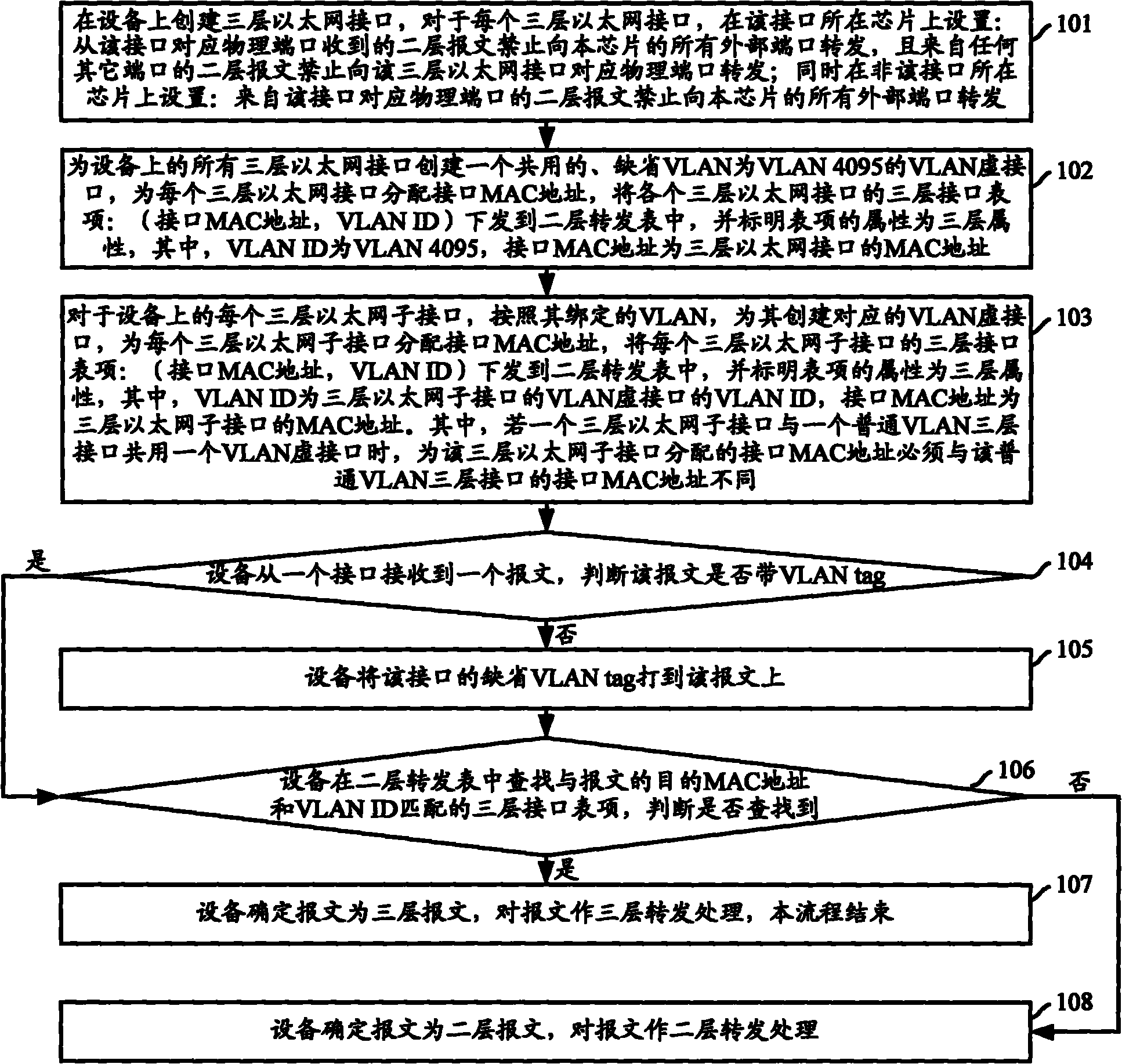
[0052] figure 1 The flow chart of the method for creating a three-layer interface provided by the embodiment of the present invention, such as figure 1 As shown, the specific steps are as follows:

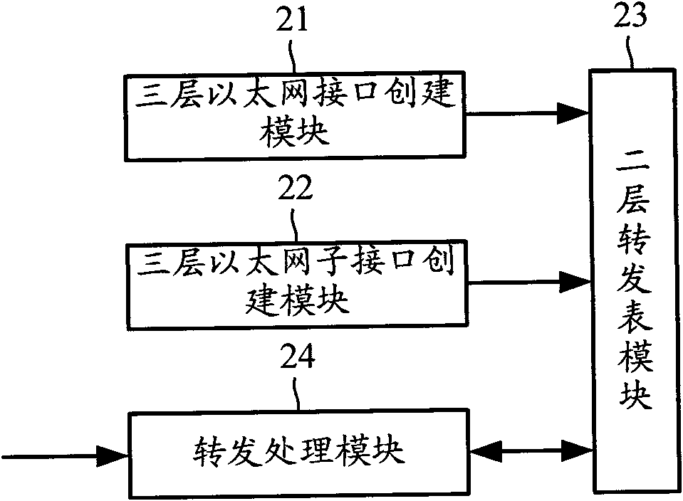
[0053] Step 101: Create a layer-3 Ethernet interface on the device. For each layer-3 Ethernet interface, set on the chip where the interface is located: the layer-2 message received from the corresponding physical port of the interface is prohibited from sending to all external ports of the chip. Port forwarding, and Layer 2 packets from any other port are prohibited from being forwarded to the physical port corresponding to the Layer 3 Ethernet interface; at the same time, it is set on the chip where the interface is not located: Layer 2 packets from the physical port corresponding to the interface are prohibited from forwarding to the p...


PUM


Abstract

The invention discloses a method and a unit for creating a layer three interface. The method comprises the following steps of: creating a shared default virtual local area network (VLAN) virtual interface for all layer three Ethernet interfaces on equipment, allocating interface media access control (MAC) addresses to each layer three Ethernet interface, and creating layer three interface table entries of each layer three Ethernet interface, wherein the layer three interface table entries comprise the interface MAC address and a VLAN identifier (ID); for each layer three Ethernet sub-interface on the equipment, creating a corresponding VLAN virtual interface according to a VLAN bound with the layer three Ethernet sub-interface, allocating the interface MAC addresses to each layer three Ethernet sub-interface, and creating the layer three interface table entries of each layer three Ethernet sub-interface, wherein the layer three interface table entries comprise the interface MAC address and the VLAN ID; and when the equipment receives a message from an interface, searching for the three layer interface table entries matched with a destination MAC address and a VLAN label of the message, and if the matched layer three interface table entries are found, performing layer three forwarding processing on the message. By the method and unit, the creation of the layer three interface can be realized without preserving the VLAN, and the VLAN configuration and use of a user may not be limited.

Description

technical field [0001] The invention relates to the technical field of message transmission, in particular to a method and a unit for creating a three-layer interface. Background technique [0002] Generally, the Ethernet interface supported on the switch device is a Layer 2 Ethernet interface. This type of interface is a physical interface on the device, working at the data link layer, processing layer-2 protocols, and implementing layer-2 fast forwarding; correspondingly, a layer-3 Ethernet interface is also a physical interface on the device, working on the network layer, which can configure Internet Protocol (IP, Internet Protocol) addresses, process Layer 3 protocols, and provide routing functions. [0003] Some Ethernet interfaces can work in Layer 2 mode (bridge) or Layer 3 mode (route) according to the different processing levels of the data packets received by the interface. Such an interface is called a Layer 2 / 3 switchable Ethernet interface. When the Ethernet ...

Claims


Application Information

Patent Timeline
IPC IPC(8): H04L12/56H04L12/46H04L29/12H04L49/111H04L45/74
CPCH04L49/00H04L61/2038H04L12/56H04L12/4679H04L29/12H04L12/46H04L61/6022H04L61/5038H04L2101/622H04L49/354
Inventor 王明辉李捷黄易
Owner NEW H3C TECH CO LTD
Why Eureka
Try Eureka