
Cover panel for capturing solar energy

A panel and metal plate technology, applied in the field of the top panel of solar collectors, can solve the problems of being easily affected by mechanical action, sealing, difficult panel connection, etc.

Inactive Publication Date: 2011-08-17
CUPA INNOVACION S L U
View PDF2 Cites 0 Cited by
  • Summary
  • Abstract
  • Description
  • Claims
  • Application Information

AI Technical Summary

Problems solved by technology

As in the previous case, such panels require special transparent sheets as covering materials, and their installation requires skilled workers
And it is difficult to seal the connection between the panels, and it is also susceptible to mechanical action

Method used


Image

  • Cover panel for capturing solar energy
  • Cover panel for capturing solar energy
  • Cover panel for capturing solar energy

Examples


Embodiment Construction

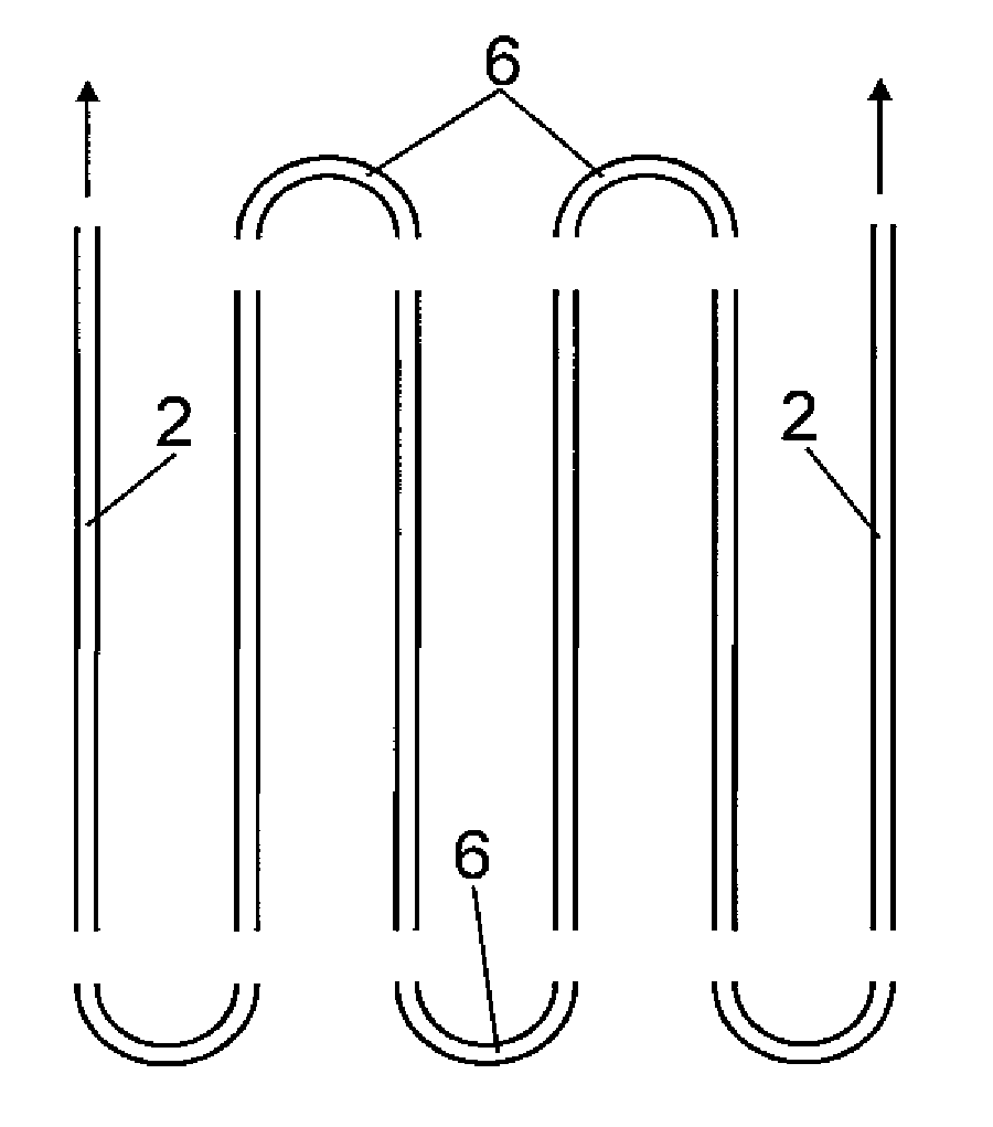
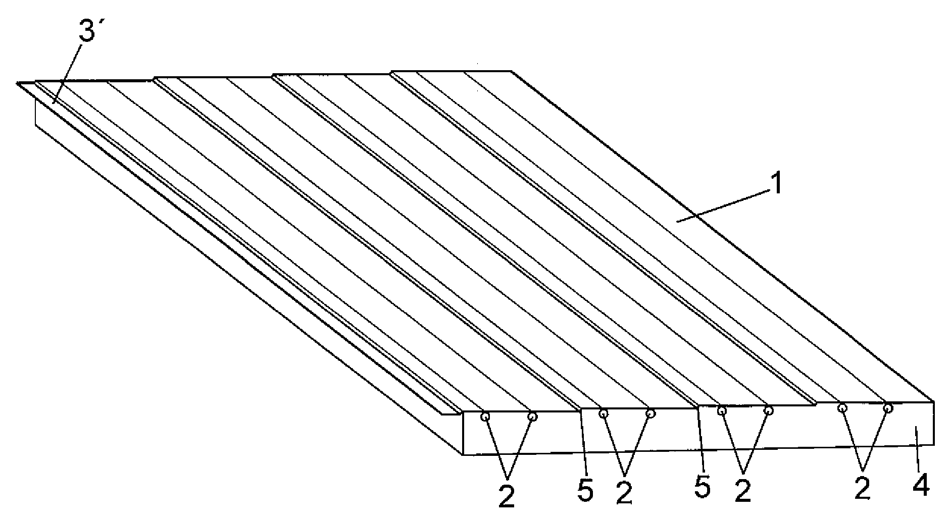
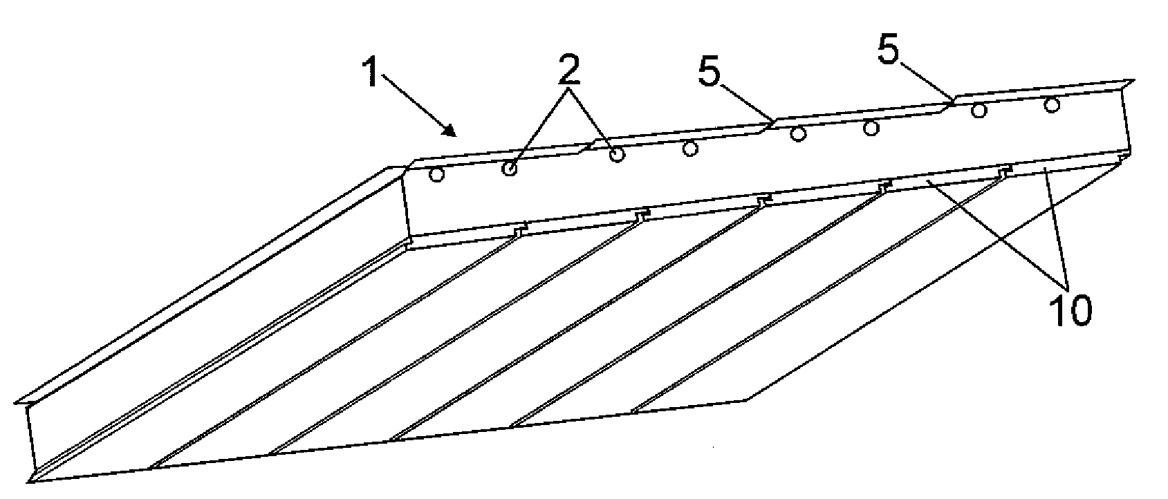
[0034] as available from Figure 1 to Figure 3 As can be seen in , the solar collector top panel of the present invention comprises a metal plate 1 having a good heat transfer coefficient, to one of the faces of which a series of parallel conduits 2 are fixed along the The entire length of the conduit contacts the plate 1 and is covered by a layer 4 of insulating material.

[0035] as available from image 3 As can be seen more clearly, a flashing 3 is inserted between the metal plate 1 and the layer of insulating material 4, and said plate 3 protrudes from the edge with a strip 3' which will serve as overlapping means to ensure these continuous Water resistance in joints between panels or joints with other parts of the product.

[0036] The tube 2 can be in contact with the metal plate 1 and constitute a separate piece of this metal plate, and can be fixed to said plate, for example by welding, mechanical coupling, stamping or any other system. These ducts 2 can also form ...


PUM


Abstract

The invention provides a cover panel for capturing solar energy, which comprises a sheet (1) of metallic nature, a series of metal ducts (2) fixed to said sheet, and a layer of insulating material (4) which covers said ducts. The set of ducts defines a continuous circuit which can be connected to another adjacent circuit or to the duct of an external circuit.

Description

technical field [0001] The present invention relates to a solar collector roof panel and in particular to the design of a roof made of slate sheets, the cover of which panel has the same finish and appearance as a conventional cover and is suitable for all types of covering materials and finishes . Background technique [0002] Solar heat absorber panels are known for roofs, which panels are designed as an energy saving device. [0003] From the patent document US 2004098932 is known a solar absorber panel for roofs, this panel has an outer layer made of tiles transparent to solar radiation and an inner layer made of metal strips or another type strips that absorb solar radiation and transmit it to tubes welded to each of these strips. This system requires a special transparent sheet as the covering material and changes the appearance of the top. Furthermore, this type of panel is slow to install, has low robustness and is susceptible to mechanical action. [0004] GB 24...

Claims


Application Information

Patent Timeline
Patent Type & Authority Applications(China)
IPC IPC(8): F24J2/04F24J2/26F24S10/75
CPCY02B10/20F24J2002/0053F24J2/045Y02E10/44F24J2/268F24J2/4614F24S2020/12F24S20/67F24S10/755F24S40/44Y02A30/60F24S10/753
Inventor J.弗南德斯弗南德斯
Owner CUPA INNOVACION S L U
Learn More