
Centrifuge with a self-emptying centrifuge drum

A centrifuge and centrifugal technology, applied to centrifuges with rotating drums, centrifuges, etc., can solve the problems of increased cost, best emptying performance, and failure to realize the opening stroke of piston sliders. Achieving height reduction and optimizing emptying performance

Active Publication Date: 2011-08-24
GEA MECHANICAL EQUIP
View PDF10 Cites 3 Cited by
  • Summary
  • Abstract
  • Description
  • Claims
  • Application Information

AI Technical Summary

Problems solved by technology

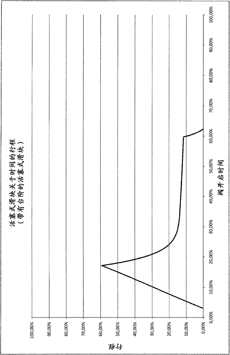
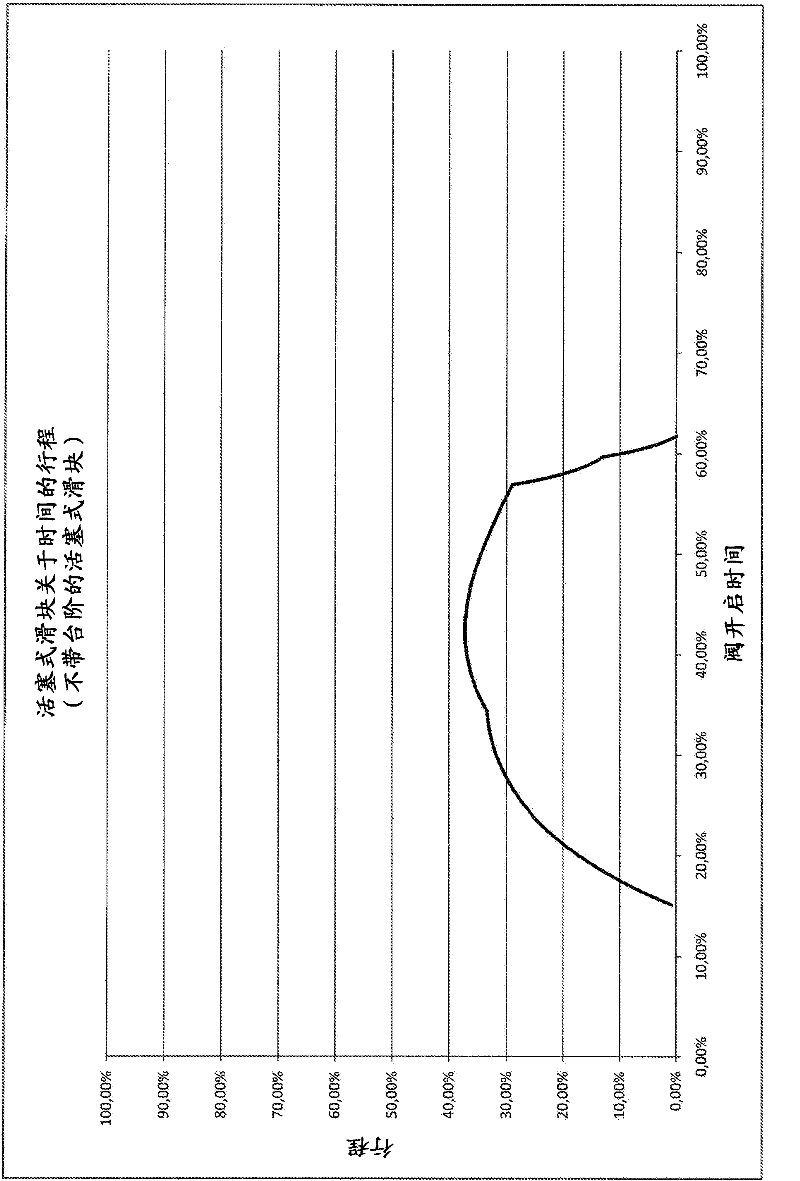
Despite the metering device, the emptying performance of this construction is not always optimal, since a very large opening stroke of the piston slide is not achieved (see image 3 )
In addition, the metering devices used lead to increased costs

Method used


Image

  • Centrifuge with a self-emptying centrifuge drum
  • Centrifuge with a self-emptying centrifuge drum
  • Centrifuge with a self-emptying centrifuge drum

Examples


Embodiment Construction

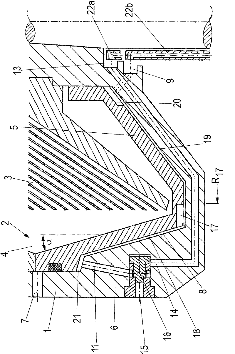
[0014] The centrifuged material (solid-liquid mixture) to be treated passes through the central inlet 22 (see in this regard Figure 4 configuration shown schematically) is conveyed to a rotatable drum 1 of a (dish) separator with a vertical axis of rotation, which has a centrifuge space 2 which is divided into a separation space 3 and a solid material space 4 .

[0015] The solid material space 4 is delimited on one side (here downwards) by an axially displaceable piston slide 5 which, during its axial movement, opens or closes the Throwing opening 7 for solid material.

[0016] Between the piston slide 5 and the drum shell 6 or the lower part of the drum, a closed cavity 8 into which a closed fluid can be input is constructed.

[0017] Via the injection chamber 9 and the supply line 10 , the closure liquid can be introduced into the closure chamber 8 . This closed liquid can be discharged from the drum 1 through one or more discharge lines 11, in which one or more piston v...


PUM


Abstract

A centrifuge with a self-emptying centrifuge drum, with discharge openings (7) designed into the drum shell (6) thereof, said openings exiting from a solids chamber (4) and being closable by way of an axially moving piston slide (6), wherein a closing chamber (8) to which closing fluid can be applied is associated with the piston slide (5), said chamber is capable of being emptied by actuating one or more hydraulic valves (12) using opening fluid, wherein the closing chamber (8) comprises at least one or more recesses (17), in the proximity of which the closing chamber (8) has a larger closing chamber height than in the remaining area thereof outside the recesses (17).

Description

technical field [0001] The invention relates to a centrifugal separator with a self-emptying centrifugal bowl according to the preamble of claim 1 . Background technique [0002] A centrifugal separator with a self-emptying centrifugal bowl is known from DE-OS 19 09 996 . Further developed constructions are shown in DE 32 08 808A1, 32 40 093A1, DE 35 09 139C1, DE 35 24 731C1 and DE 36 07 526A1. With the aid of these solutions under the designation Hydrostop, it is possible to precisely control, in particular partial emptying, but it involves a correspondingly more complex construction. [0003] It is also known to control a piston valve for intermittently opening a closed chamber by means of a metering device arranged outside the drum. Despite the metering device, the emptying performance of this construction is not always optimal, since a very large opening stroke of the piston slide is not achieved (see image 3 ). Furthermore, the metering devices used lead to increase...

Claims


Application Information

Patent Timeline
Patent Type & Authority Applications(China)
IPC IPC(8): B04B1/14B04B1/18
CPCB04B1/14B04B1/18
Inventor W·马克尔H·蒂茨B·特魏
Owner GEA MECHANICAL EQUIP
Learn More