Inductive load power switching circuits

A technology of switches and switching devices, which is applied in the field of power switching circuits and can solve problems such as increasing power loss and large switching losses

Active Publication Date: 2011-08-24
TRANSPHORM INC
View PDF5 Cites 38 Cited by
  • Summary
  • Abstract
  • Description
  • Claims
  • Application Information

AI Technical Summary

Problems solved by technology

However, parasitic diode 63 typically has much poorer switching characteristics and suffers greater switching losses tha...

Method used


Image

  • Inductive load power switching circuits
  • Inductive load power switching circuits
  • Inductive load power switching circuits

Examples


Embodiment Construction

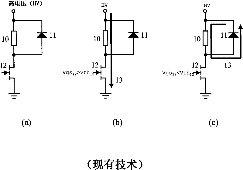
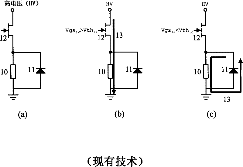
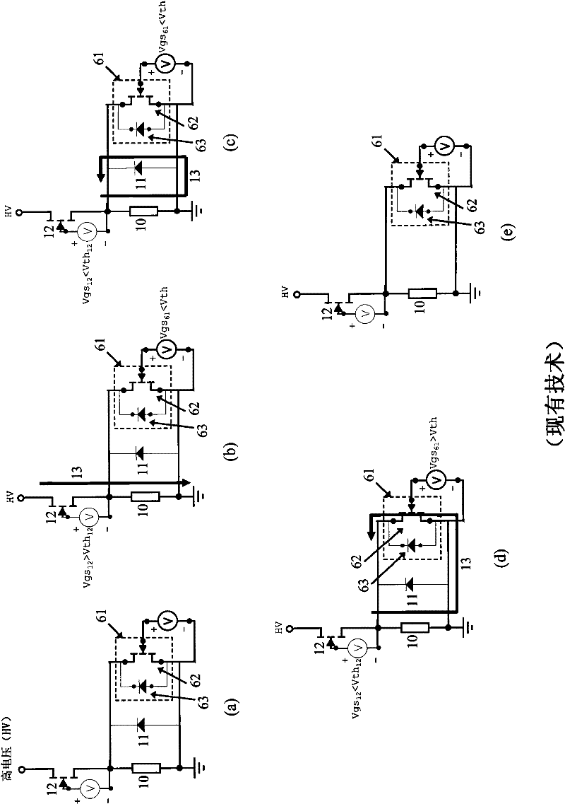
[0031] The following describes the low-side and high-side switches and the circuits they comprise, which, in Figure 1-3 The freewheeling diode shown in is replaced by a switching device such as a transistor. exist Figure 5 Examples are shown in a and 6a, where, Figure 5 a includes the low-side switch, and Image 6 a includes the high-side switch. exist Figure 5 a and 6a, in figure 1 with 2 The freewheeling diode used in the circuit has been replaced by switching device 41. In some embodiments, this device may be the same switching device 42 used to modulate the current path. Figure 5 b and 6b illustrate the current path when switching device 42 is biased on (high) and switching device 41 is biased off (low). Figure 5 c and 6c show the current paths when the switching device 42 is switched off. Switching device 41 may be an enhancement mode device, where the threshold voltage V th >0, or the switching device 41 can be a depletion device, where the threshold volt...


PUM


Abstract

Power switching circuits including an inductive load and a switching device are described. The switches devices can be either low-side or high-side switches. Some of the switches are transistors that are able to block voltages or prevent substantial current from flowing through the transistor when voltage is applied across the transistor.

Description

technical field [0001] This invention relates to power switching circuits, and more particularly, to power switching circuits using inductive loads. Background technique [0002] A single-sided switch is a switch configuration in which a switching device is used to connect a load to a node at a low potential - a "low-side" switch, or a load to a node at a high potential - a "high-side" switch. exist figure 1 The low-side configuration is shown in a, and the figure 2 A high-side configuration is shown in a, where nodes at high potential are represented by high voltage (HV) sources and nodes at low potential are represented by ground terminals. In both cases, when the load 10 is an inductive load, a freewheeling diode 11 (sometimes called a flyback diode) is required to provide a path for the freewheeling load current when the switching device is turned off. For example, as in figure 1 As shown in b, when the device threshold voltage is applied by V th Large gate-source ...

Claims


Application Information

Patent Timeline
IPC IPC(8): H03K17/64H03K17/30
CPCG05F1/70H03K17/08142Y10T29/49117
Inventor 詹姆斯·霍尼亚
Owner TRANSPHORM INC
Why Eureka
Try Eureka