Drawer structure with manual-free release lock

A manual and drawer technology, which is applied to drawers, furniture parts, household appliances, etc., can solve the problems of deformation of elastic elements, insufficient friction of slide rails and cushioning, slide table cannot be locked by locking arms, etc., to prolong service life, The effect of reduced assembly accuracy and reliable locking and releasing structure

Inactive Publication Date: 2013-02-20
刘燕
View PDF1 Cites 0 Cited by
  • Summary
  • Abstract
  • Description
  • Claims
  • Application Information

AI Technical Summary

Problems solved by technology

[0002] Chinese Patent No. 200510123743.9 is a drawer structure with a hands-free release lock. The locking unit of this structure can be well controlled by the braking unit so that the slide table can slide out of the drawer cavity smoothly, but the locking unit is through two The two joint ends of the lock arm clamp the positioning post on the bottom surface of the slide table to achieve locking. This requires the locking unit and the positioning post to be installed very accurately, otherwise the positioning post cannot enter the two joint ends. Due to the long and frequent use, The gap between the locking unit, the base and the sliding table and the elastic element in between will be deformed, so that the sliding table cannot be locked by the locking arm
[0003] The sliding table in the above-mentioned patent product can only rely on the friction generated by the slide rails to slow down the sliding table sliding speed from the drawer cavity. When the sliding table bears a large gravity, the sliding table sliding speed is very fast. Insufficient friction has been buffered

Method used


Image

  • Drawer structure with manual-free release lock
  • Drawer structure with manual-free release lock
  • Drawer structure with manual-free release lock

Examples


Embodiment Construction

[0022] The present invention will be described in further detail below in conjunction with the accompanying drawings and embodiments.

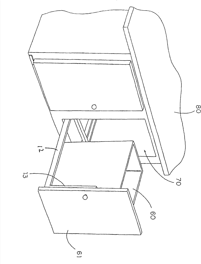
[0023] Embodiment, in order to describe the structure of this embodiment clearly, the present embodiment is set in a cabinet 80 for description below, combined with figure 1 with figure 2 , the cabinet 80 can be a cabinet of common structure and shape, which has at least one drawer cavity 70, wherein the drawer release device is preferably arranged to fit properly with the drawer cavity 70 and can be received by the drawer cavity 70, so that the drawer can be releasably placed 60 in the drawer cavity 70. The drawer 60 is installed above the slide table 12 , and the drawer panel 61 is installed on the two drawer panel support members 13 .

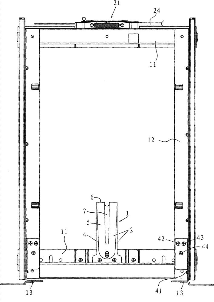
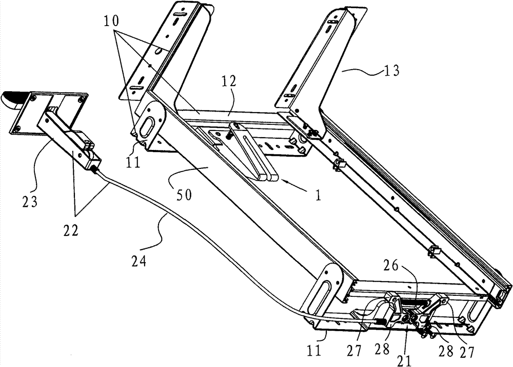
[0024] combine Figure 2 to Figure 7 , a drawer structure with a hands-free release lock, including a support frame 10 and a locking device, the support frame is used to support the drawer in the drawer ...


PUM


Abstract

The invention relates to a drawer releasing device which can automatically release a drawer by simple braking on the position far away from the drawer. The drawer structure comprises a support frame and a locking device, wherein the support frame comprises a substrate and a sliding table; the sliding table and the substrate are in sliding fit and are installed on the substrate in an inclined mode; the locking device comprises a locking unit and a braking unit, wherein the locking unit comprises two locking arms which can be installed on the substrate in a rotatable mode; each locking arm is provided with a junction end and a driving end, wherein the driving end is connected with a brake cable; a magnetizer is arranged between two junction ends of the two locking arms and the sliding table correspondingly matched with the locking arms, so that the sliding table and the two junction ends of the two locking arms can mutually attract when the sliding table slides into the cavity of the drawer to lock the sliding table; and when a brake lock is driven to cause the two driving ends of the locking arms to oppositely move, two junction ends simultaneously rotate to cause the two junction ends to separate from the sliding table so as to realize that the sliding table can freely slide out of the cavity of the drawer. The locking unit is simple to assemble, assembling precision is lowered, and locking and releasing structure is reliable. The impact force of the substrate can be effectively eliminated, the substrate and a cabinet body are protected, and the service life of the substrate and the cabinet body can be prolonged.

Description

technical field [0001] The present invention relates to drawers, and more particularly to a drawer release device capable of releasing a drawer remotely from the drawer by simple actuation. Background technique [0002] Chinese Patent No. 200510123743.9 is a drawer structure with a hands-free release lock. The locking unit of this structure can be well controlled by the braking unit so that the slide table can slide out of the drawer cavity smoothly, but the locking unit is through two The two joint ends of the lock arm clamp the positioning post on the bottom surface of the slide table to achieve locking. This requires the locking unit and the positioning post to be installed very accurately, otherwise the positioning post cannot enter the two joint ends. Due to the long and frequent use, The gap between the locking unit, the base and the sliding table and the elastic element arranged therebetween will be deformed, so that the sliding table cannot be locked by the locking a...

Claims


Application Information

Patent Timeline
Patent Type & Authority Patents(China)
IPC IPC(8): A47B88/04
Inventor 宋振谦
Owner 刘燕
Why Eureka
Try Eureka