Attached mechanism of small star lander
A technology for landers and stars, which is applied to the landing device of space vehicles and the system for space vehicles to return to the earth's atmosphere, etc. It can solve the problems that the landers are easy to float away and the surface gravity of small stars is small, and achieve the effect of preventing damage
- Summary
- Abstract
- Description
- Claims
- Application Information
AI Technical Summary
Problems solved by technology
Method used
Image
Examples
specific Embodiment approach 1
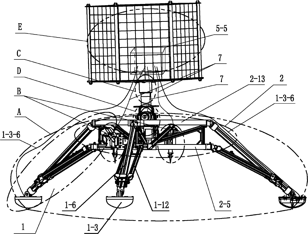
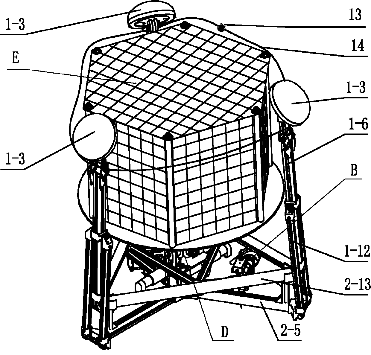
[0030] Specific implementation mode one: combine Figure 1-Figure 12 , Figure 14-Figure 18 with Figure 20-Figure 23 Describe this embodiment, the small star lander attachment mechanism of this embodiment includes a landing mechanism A, a universal joint mechanism D, a buffer mechanism C, an instrument platform E and one or two anchor positioning systems B,
[0031] The landing mechanism A includes a triangular space truss support 2 and three landing legs 1; the three landing legs 1 are distributed around the triangular space truss support 2;
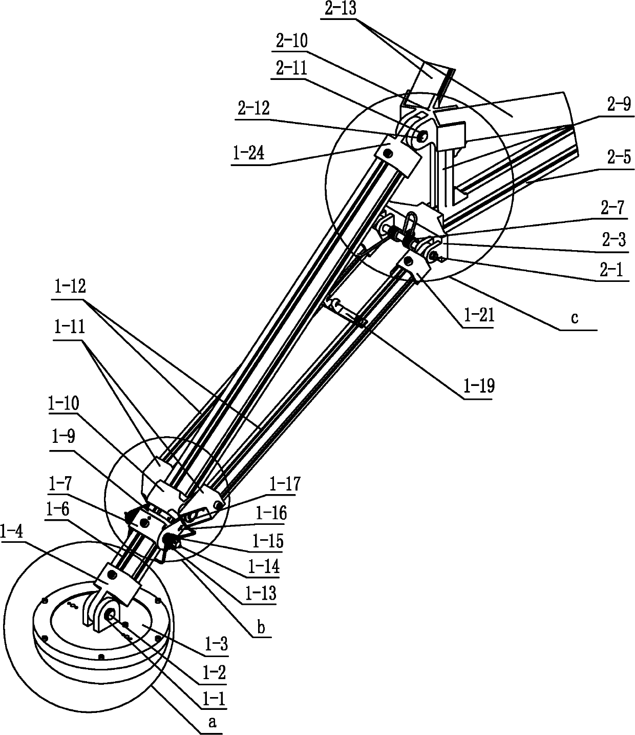
[0032] Each landing leg 1 includes a retaining ring 1-1 at the shaft end of the landing leg, a connecting shaft 1-2 of the landing leg, a landing leg 1-3, a main landing leg joint 1-4, a main landing leg 1-6, and a locking block 1- 7. Two locking parts installation shaft 1-8, slider 1-10, locking spring 1-13, main landing leg space truss bracket joint 1-24, two auxiliary landing leg slider joints 1-11, Two auxiliary landing legs 1-1...
specific Embodiment approach 2
[0053] Specific implementation mode two: combination Figure 3-Figure 7 Describe this embodiment, the lower end of the main landing leg 1-6 of this embodiment is welded with the main landing leg joint 1-4, the upper end of the main landing leg 1-6 is welded with the main landing leg space truss type support joint 1-24, lock The tight block 1-7 is welded on the lower part of the main landing leg 1-6, the auxiliary landing leg slider joint 1-11 is welded to one end of the auxiliary landing leg 1-12, and the other end of the auxiliary landing leg 1-12 is welded with an auxiliary landing Leg space truss type support joint 1-21, two adjacent ends of two adjacent triangular support rods 2-13 are welded together through a triangular support joint 2-10, and the three star-shaped support rods 2-5 star Arranged in a shape and welded together through the center joint 2-6; the upper end of each connecting pillar 2-9 is welded together with a triangular bracket joint 2-10 through a first c...
specific Embodiment approach 3
[0054] Specific implementation mode three: combination Figure 3-Figure 7 Describe this embodiment, the lower end of the main landing leg 1-6 of this embodiment and the main landing leg joint 1-4 are connected together by screws, and the upper end of the main landing leg 1-6 is connected to the main landing leg space truss type support joint 1-4. 24 are connected together by screws, the locking block 1-7 is fixed on the lower part of the main landing leg 1-6 by screws, and the auxiliary landing leg slider joint 1-11 is connected with one end of the auxiliary landing leg 1-12 by screws The other end of the auxiliary landing leg 1-12 is connected with the auxiliary landing leg space truss type support joint 1-21 by screws, and the two adjacent ends of two adjacent triangular support rods 2-13 are connected with a triangular support joint 2-21 10 are connected together by screws, and the three star-shaped bracket rods 2-5 are arranged in a star shape and connected with the centra...
PUM
 Abstract
Description
Claims
Application Information
 - R&D
- Intellectual Property
- Life Sciences
- Materials
- Tech Scout
- Unparalleled Data Quality
- Higher Quality Content
- 60% Fewer Hallucinations
Browse by: Latest US Patents, China's latest patents, Technical Efficacy Thesaurus, Application Domain, Technology Topic, Popular Technical Reports.
© 2025 PatSnap. All rights reserved.Legal|Privacy policy|Modern Slavery Act Transparency Statement|Sitemap|About US| Contact US: help@patsnap.com


