
High-accuracy detection and calibration device and method of inertial orientating equipment

A technology of directional equipment and calibration device, which is applied in the direction of measuring device, satellite radio beacon positioning system, radio wave measurement system, etc., can solve the problems of complex operation and calculation methods, detection and calibration work restrictions, etc., and achieves convenient use, high cost performance, The effect of maintaining orientation accuracy

Active Publication Date: 2011-08-31
北京星网宇达科技股份有限公司
View PDF5 Cites 19 Cited by
  • Summary
  • Abstract
  • Description
  • Claims
  • Application Information

AI Technical Summary

Problems solved by technology

[0005] 1) This method can only be carried out in the area where the true north datum or two standard geodetic coordinate points are set;
[0006] 2) The operation and calculation method is complex and requires professionals to complete, which limits the detection and calibration work to a certain extent

Method used


Image

  • High-accuracy detection and calibration device and method of inertial orientating equipment
  • High-accuracy detection and calibration device and method of inertial orientating equipment
  • High-accuracy detection and calibration device and method of inertial orientating equipment

Examples


Embodiment Construction

[0030] The present invention will be described in further detail below in conjunction with the accompanying drawings.

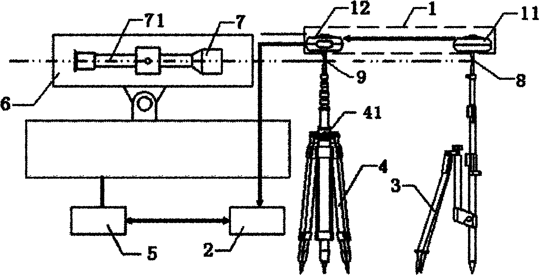
[0031] Such as figure 1 As shown, in this embodiment, the inertial orientation device 5 to be tested is connected to the carrier 6 , and the direct sight mirror 7 is arranged on the carrier 6 , and an optical axis 71 is arranged at the center of the direct sight mirror 7 .

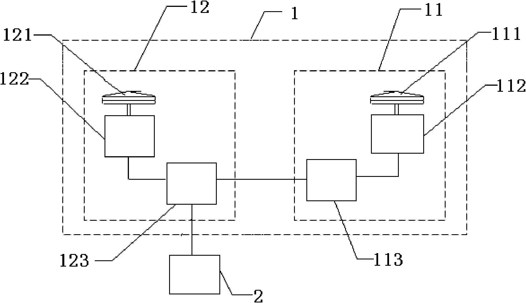
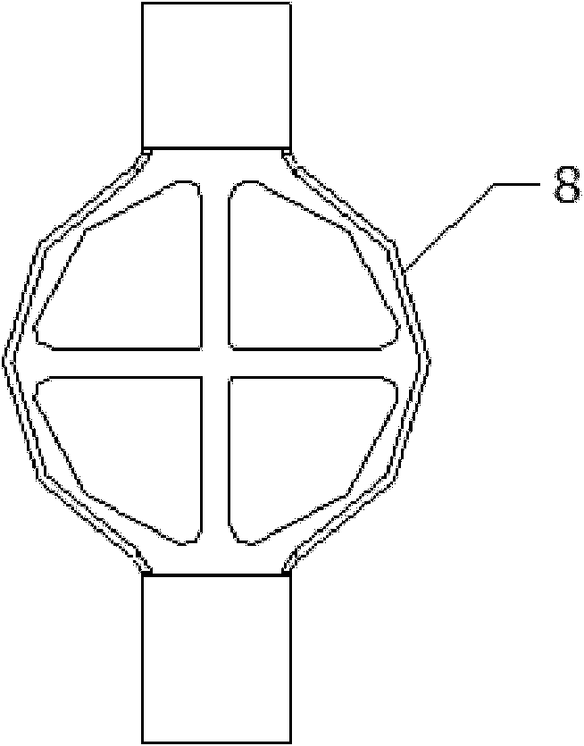
[0032] Such as figure 1 As shown, the high-precision detection and calibration device of the inertial orientation equipment of the present invention includes a positioning and orientation solution processing system 1 and a display control terminal 2 composed of a GPS reference station 11 and a GPS mobile station 12. The lower end of the GPS reference station 11 is connected with Base station sight 8, the lower end of base station sight 8 is connected with base station bracket 3; A direction fine-tuning mechanism 41 is also arranged on the stand bracket 4 . The display control terminal ...


PUM


Abstract

The invention discloses a high-accuracy detection and calibration device and method of inertial orientating equipment. The device comprises a positioning and orientating resolving processing system, a display control terminal, a mobile station bracket and a reference station bracket, wherein the positioning and orientating resolving processing system consists of a GPS (Globe Positioning System) mobile station and a GPS reference station; the display control terminal is connected with the positioning and orientating resolving processing system in a wireless way; the upper end of the mobile station bracket is provided with a mobile station aiming tool connected with the GPS mobile station; and the upper end of the reference station bracket is provided with a reference station aiming tool connected with the GPS reference station. By adopting the high-accuracy detection and calibration device and method of the inertial orientating equipment, calibration of the inertial orientating equipment is realized by adopting a satellite orientating technology, and limits on the detection and calibration of the inertial orientating equipment due to adoption of a true north or indirect true north finding reference method are complemented; a static relative positioning and orientating method is adopted, so that limits of regions and environments are eliminated and flexible movement is realized; and the device and the method have the advantages of high positioning accuracy, high cost performance, easiness of operation, convenience of using and the like.

Description

technical field [0001] The invention relates to a detection and calibration device and a method thereof for orientation equipment, in particular to a high-precision detection and calibration device and a detection and calibration method for inertial orientation equipment. Background technique [0002] At present, most of the autonomous orientation equipment commonly used in the military is based on the principle of inertial measurement, that is, the use of high-precision gyroscopes to sense the horizontal component of the earth's rotation motion, and according to the change law of the angle between the sensitive axis and the north direction, the data is processed to obtain the true north direction , in this kind of equipment, parameters such as the zero position and scale factor of the gyroscope will change with the storage time and the use environment, and drift with the temperature, which is determined by its physical characteristics. This characteristic of the gyroscope is...

Claims


Application Information

Patent Timeline
IPC IPC(8): G01C25/00G01S19/53
Inventor 迟家升宋光威尚修磊
Owner 北京星网宇达科技股份有限公司
Learn More