Radio-frequency-identification (RFID)-based closed circuit television system and monitoring method

A closed-circuit television and monitoring front-end technology, applied in the field of RFID-based closed-circuit television systems and monitoring, to achieve the effect of fast tracking, easy implementation and low cost

Inactive Publication Date: 2011-08-31
李兆全
View PDF0 Cites 15 Cited by
  • Summary
  • Abstract
  • Description
  • Claims
  • Application Information

AI Technical Summary

Problems solved by technology

However, there are no examples of applying this technolo

Method used


Image

  • Radio-frequency-identification (RFID)-based closed circuit television system and monitoring method
  • Radio-frequency-identification (RFID)-based closed circuit television system and monitoring method
  • Radio-frequency-identification (RFID)-based closed circuit television system and monitoring method

Examples


no. 1 example

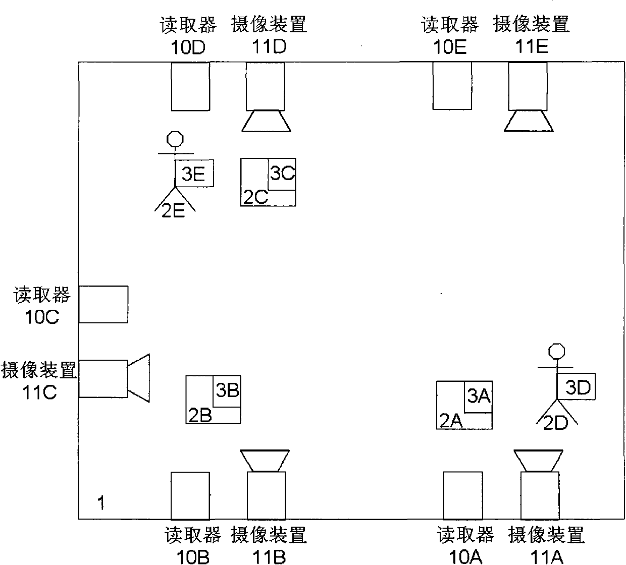
[0056] figure 1 It is a schematic diagram of a monitoring site installed with a closed-circuit television monitoring system according to the present invention. Wherein, box 1 represents the monitoring place, such as a warehouse or a parking lot. As shown in the figure, there are monitoring objects 2A-2C in the monitoring site 1 . The monitoring targets 2A-2C are items placed in the monitoring place 1, such as goods in a warehouse or cars parked in a parking lot. The above items are attached with RFID electronic tags 3A-3C respectively. The monitoring targets 2D and 2E are persons present in the monitoring place 1, and the above persons also wear RFID electronic tags 3D and 3E respectively. For example, the above electronic tags can be set on the work clothes of the warehouse porters, and the parking lot administrator can also require the personnel entering the parking lot to receive or wear the above electronic tags. Specific identification codes are stored in the RFID ele...

no. 2 example

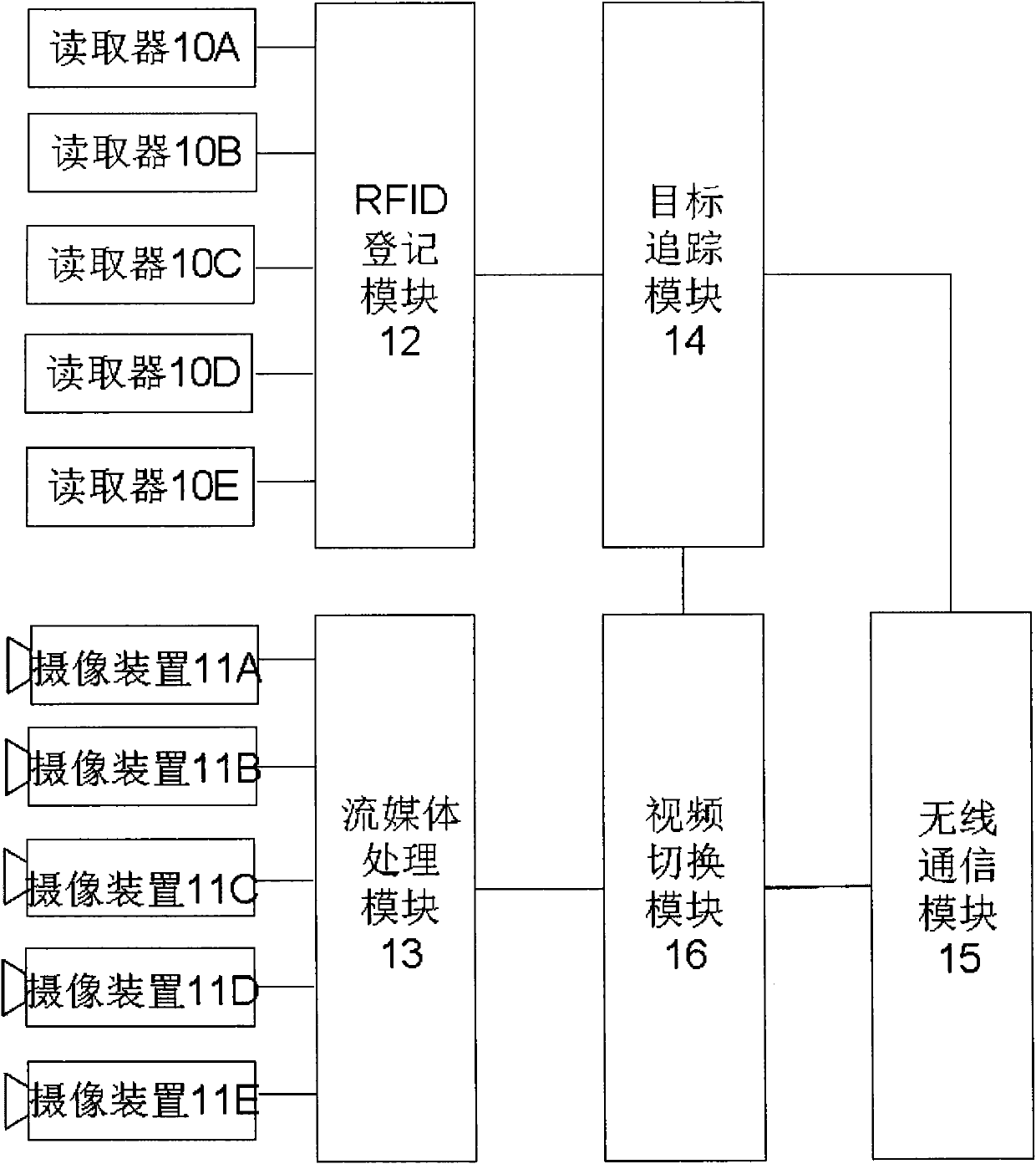
[0074] Image 6 It is a schematic structural diagram of an RFID-based closed-circuit television system according to the second embodiment of the present invention. As shown in the figure, in this embodiment, the system includes readers 20A-20E, camera devices 21A-21E, RFID registration module 22, streaming media processing module 23, target tracking module 24, wireless communication module 25, and video switching Module 26. The working mode of the above modules is the same as that of the first embodiment, and will not be repeated for the sake of brevity.

[0075] The difference between the second embodiment and the first embodiment is that the target tracking module 24 inquires the RFID registration module 22 in real time and judges whether the identification code corresponding to the monitoring front-end number of each reader 20A-20E occurs change; and generate a switch control command according to the number of the monitoring front end corresponding to the change in the id...


PUM


Abstract

The invention relates to a radio-frequency-identification (RFID)-based closed circuit television system and an RFID-based monitoring method. The system comprises RFID tags (3A to 3E), a plurality of groups of monitoring front-ends consisting of readers (10A to 10E) and photographic devices (11A to 11E), an RFID registration module (12), a stream media processing module (13), a target tracking module (14), a wireless communication module (15) and a video switching module (16). In the system and the monitoring method, the RFID tags are attached to a monitoring target, identification codes are read from the RFID tags by the reader, and corresponding video streams are retrieved according to the identification codes for display on a monitor console, thereby realizing target tracking in the closed circuit television system based on an RFID technology. The system and the method have the advantages of capability of realizing the automatic switching of monitoring pictures and the automatic identification of the monitoring target, low cost, high tracking speed and accuracy, and convenience of conventional system upgrading and transformation, and are easy to implement.

Description

technical field [0001] The present invention relates to a closed-circuit television monitoring technology, and more particularly, to an RFID-based closed-circuit television system and a monitoring method. Background technique [0002] Closed-circuit television (CCTV) monitoring technology has important applications in security, personnel management, production monitoring and other aspects. Existing closed-circuit television systems usually use multiple camera devices distributed in different locations to take real-time pictures of the monitoring area. The monitoring pictures obtained by multiple camera devices are processed and encoded by the streaming media module to form multiple video streams, and then transmitted to the monitoring platform and displayed on the monitor of the monitoring platform. Usually, the monitor of the monitoring platform switches between the monitoring images of the various camera devices to reflect the situation of the monitoring area. [0003] I...

Claims


Application Information

Patent Timeline
IPC IPC(8): H04N7/18G06K7/00
Inventor 李兆全
Owner 李兆全
Why Eureka
Try Eureka