Air conditioner

An air conditioner and air-conditioning technology, which is applied in air-conditioning systems, mechanical equipment, space heating and ventilation, etc., can solve problems such as user anxiety, control software development burden, and inability to confirm, and achieve the effect of improving energy saving or satisfaction

Active Publication Date: 2014-03-12
HITACHI JOHNSON CONTROLS AIR CONDITIONING INC
View PDF12 Cites 0 Cited by
  • Summary
  • Abstract
  • Description
  • Claims
  • Application Information

AI Technical Summary

Problems solved by technology

In this document, it is not clearly stated what kind of signal phase difference is, but taking a step back, even based on human actions, there is no record of how to process the signals generated intermittently in time series to control the air conditioner. lack of practical effect
In addition, there is no mention of the amount of activity of indoor people
[0013] In Patent Document 3, it is necessary to set the area characteristic for each detection area in advance, and this function cannot be confirmed in the test operation immediately after installation, which will cause anxiety to the user
In addition, since the determination condition of presence or absence must also be set as an area characteristic, the development burden of the control software is heavy, and the development cost will increase
Also, there is no reference to the amount of activity of the people in the room
Furthermore, when a plurality of sensors detects, there is no description on how to distinguish between the case where a person is located in an overlapping area and the case where a person is located in a non-overlapping area.

Method used


Image

  • Air conditioner
  • Air conditioner
  • Air conditioner

Examples


Embodiment 1

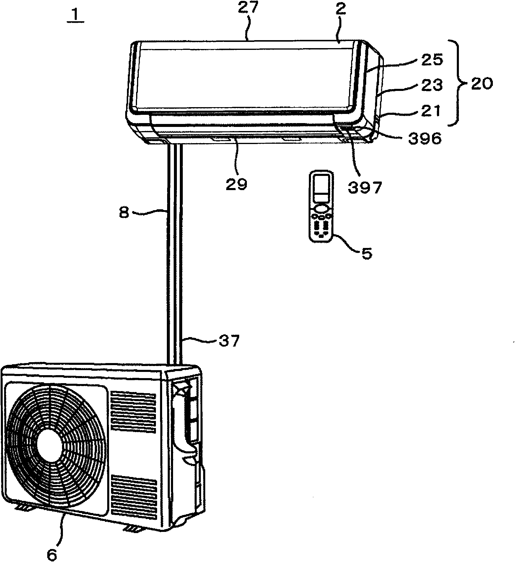
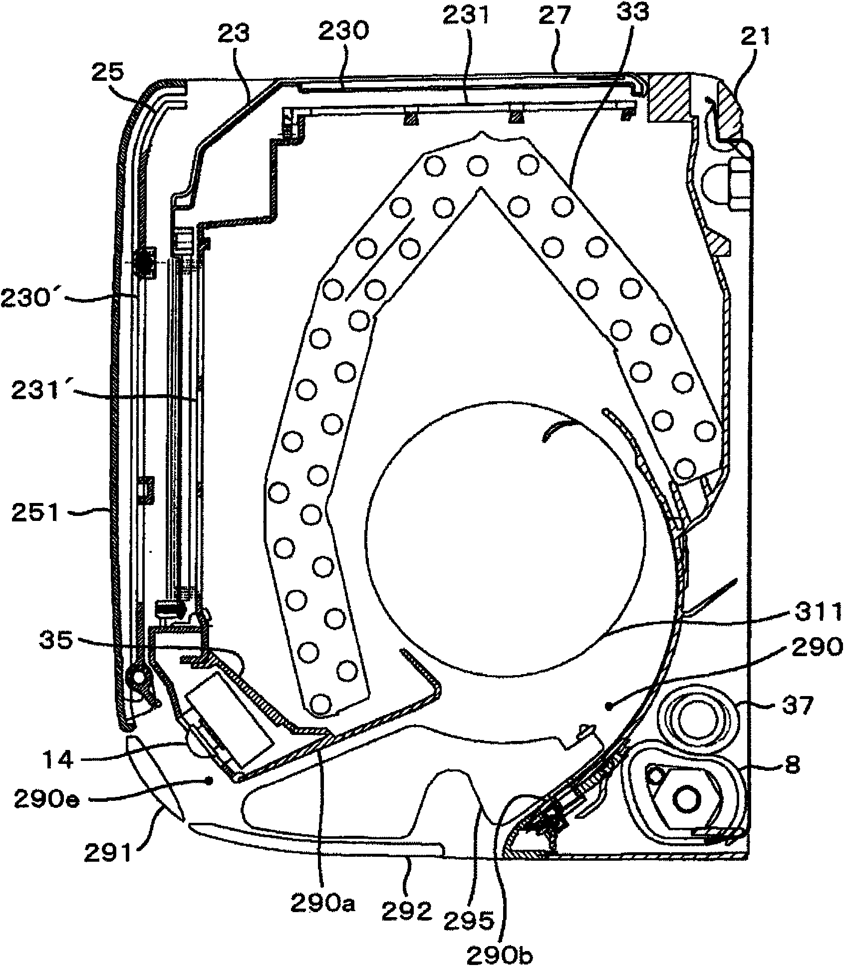
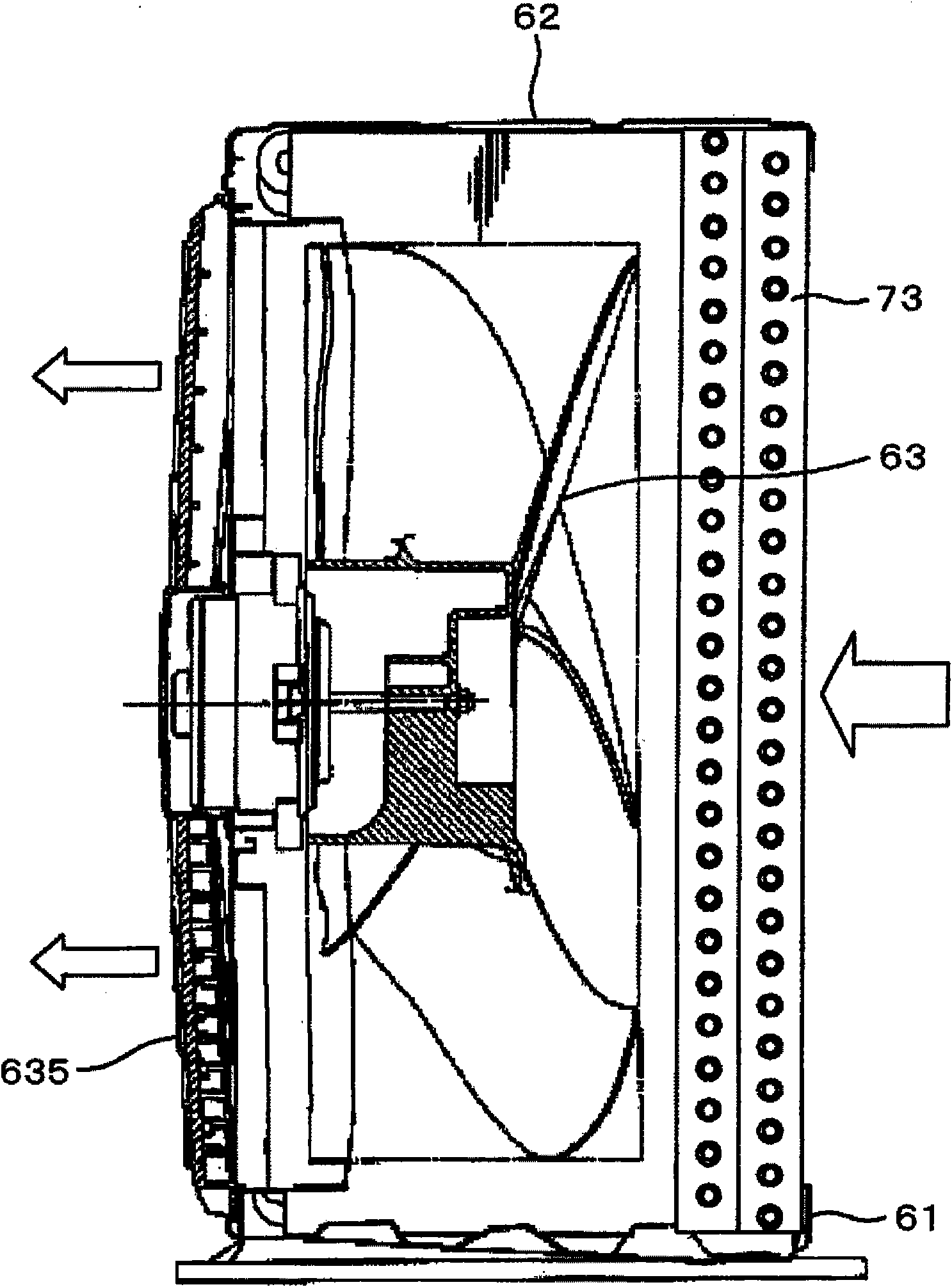
[0049] First, use Figure 1 to Figure 4 The overall structure of the air conditioner will be described. figure 1 It is a block diagram of the air conditioner of an Example. figure 2 It is a sectional view of the indoor unit of the air conditioner. image 3 It is a sectional view of the outdoor unit of the air conditioner. Figure 4 It is a refrigerant circuit diagram of the air conditioner, (a) is a diagram showing the flow direction of the refrigerant during the cooling / dehumidification operation, and (b) is a diagram showing the flow direction of the refrigerant during the heating operation.

[0050] The air conditioner 1 connects the indoor unit 2 and the outdoor unit 6 through the connecting pipe 8, and performs air conditioning in the room. With respect to the indoor unit 2, the indoor heat exchanger 33 is placed in the center of the housing base 21, and an indoor blower fan 311 of a cross-flow fan type is arranged on the downstream side of the heat exchanger 33. The ...

Embodiment 2

[0249] Next, use the embodiment 2 that increases the number of infrared sensors Figure 48 ~ Figure 50 Be explained. Figure 48 It is a detection range diagram of the infrared detection device of Example 2. Figure 49 It is the detection area division diagram of the detection device. Figure 50 It is the estimated figure of the occupied area of ​​the detection device, (a) is a schematic diagram of area division, (b) is the occupied area when the difference between a and b is large, and (c) is the case when the difference between a and b is small occupied area.

[0250] In embodiment 2, such as Figure 48 As shown, it is constituted by increasing the number of infrared sensors 410 of Embodiment 1 from two to three, and configured as: adjacent left human body detection sensor 140 and left human body detection sensor 140b, and middle human body detection sensor The detection ranges of 140b and the right human detection sensor 140c partially overlap, and the detection ranges of ...

Embodiment 3

[0260] Next, use Figure 51 ~ Figure 53 Example 3 in which the arrangement of three infrared sensors is changed will be described. Figure 51 It is a schematic diagram of the detection area of ​​the infrared detection device of Example 3. Figure 52 It is the detection area division diagram of the detection device. Figure 53 It is the estimated figure of the occupied area by the detection device, (a) is a schematic diagram of area division, (b) is the occupied area when the difference between a and b is large, and (c) is the case when the difference between a and b is small occupied area.

[0261] Such as Figure 51 As shown, in Embodiment 3, the arrangement of the human body detection sensors 140a-c in Embodiment 2 is changed, and the arrangement is as follows: the adjacent left human body detection sensor 140a, the middle human body detection sensor 140b, and the middle human body detection sensor 140b The detection range of the right human detection sensor 140c partial...


PUM


Abstract

An air conditioner has a housing having an air inlet opening and an air outlet opening, a heat exchanger placed in the housing, a fan sucking air in a room from the air inlet opening and discharging the air from the air outlet opening after causing the air to pass through the heat exchanger, horizontal louver plates placed in an outlet air flow path of the fan, vertical louver plates, and infrared detection device having at least first and second infrared sensors and estimating the presence of a person in the room by dividing the inside of the room into multiple regions. The first and second infrared sensors are arranged so that portions of the detection ranges thereof overlap each other, and depending on outputs from the first and second infrared sensors, the air conditioner determines whether the region in which the detection ranges overlap alone is a region where a person is present. Thus, the region where the person is present is distinguished without an increase in the number of human detection sensors, and the air conditioner can automatically perform comfortable operation and energy saving operation according to conditions of the person in the room.

Description

technical field [0001] The invention relates to an air conditioner equipped with an infrared sensor, in particular to the improvement of human body detection function. Background technique [0002] The air conditioner air-conditions the room by circulating the room air in a heat exchanger to be adjusted by heating, cooling, dehumidification functions, etc., and then blowing it into the room. At this time, if the conditioned air can be blown to the position where the indoor occupants are, the indoor occupants do not need to perform cumbersome operations one by one, the satisfaction of the indoor occupants is improved, and the surroundings of the indoor occupants become comfortable. Realize energy saving of air conditioners. [0003] As one of them, a method was conceived of: installing an infrared sensor on the air conditioner to detect the position of people in the room, and increasing or decreasing the wind direction, air volume, cooling and heating capacity, etc. accordin...

Claims


Application Information

Patent Timeline
Patent Type & Authority Patents(China)
IPC IPC(8): F24F11/02F24F1/0059F24F1/0083
CPCF24F11/0034F24F1/0007F24F11/30F24F2120/10F24F1/0059F24F1/0083F24F11/46F24F11/79F24F11/65
Inventor 能登谷义明永田孝夫上田贵郎松岛秀行
Owner HITACHI JOHNSON CONTROLS AIR CONDITIONING INC
Why Eureka
Try Eureka