Device and method for bending pipe with sealed end by using tension rope or plug

A technology of bending device and tensioning rope, which is applied in the field of pipe bending device, can solve problems such as unreliable sealing and forming efficiency, achieve the effect of eliminating sealing failure, improving forming efficiency, and realizing pipe end sealing

Active Publication Date: 2011-09-07
HARBIN INST OF TECH
View PDF4 Cites 14 Cited by
  • Summary
  • Abstract
  • Description
  • Claims
  • Application Information

AI Technical Summary

Problems solved by technology

[0004] The purpose of the present invention is to solve the problems of unreliable sealing and low forming efficiency in the existing pipe bending forming process with internal pressure, and further provide a pipe bending device and method that utilizes a tension rope and a plug to achieve pipe end sealing

Method used


Image

  • Device and method for bending pipe with sealed end by using tension rope or plug
  • Device and method for bending pipe with sealed end by using tension rope or plug
  • Device and method for bending pipe with sealed end by using tension rope or plug

Examples


specific Embodiment approach 1

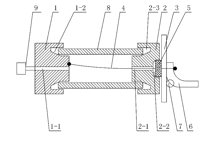
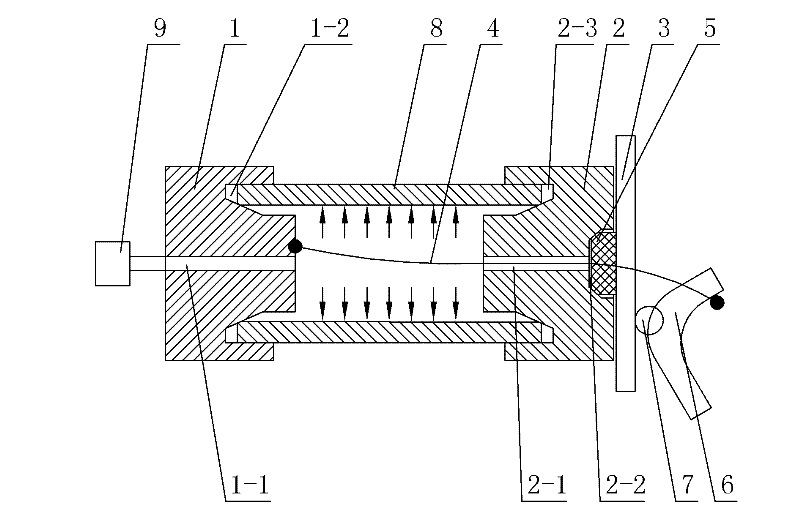
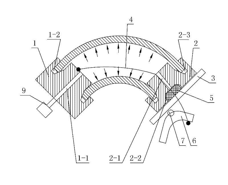
[0018] Specific implementation mode one: combine Figure 1 ~ Figure 3 Describe this embodiment, the pipe bending device of this embodiment that utilizes the tension rope and the plug to realize the sealing of the pipe end includes a booster cylinder 9, a first plug 1, a second plug 2, a pressure plate 3, a tension rope 4, Tension rope sealing ring 5, tension wrench 6 and rotating shaft 7, the first plug 1 is provided with a charging center hole 1-1, the booster cylinder 9 is connected to the charging center hole 1-1, the first plug One end face of 1 is provided with the first annular groove 1-2, the cross section of the first annular groove 1-2 is a right angle trapezoid, the outer wall of the first annular groove 1-2 is a straight wall, the first annular groove The inner wall of 1-2 is an inclined wall, the width of the groove bottom of the first annular groove 1-2 is smaller than the wall thickness of the pipe 8 to be bent, the second plug 2 is provided with a tension rope p...

specific Embodiment approach 2

[0019] Specific implementation mode two: combination Figure 1 ~ Figure 3 The present embodiment will be described, and the booster cylinder 9 of the present embodiment is a hydraulic pressure booster cylinder. Such an arrangement is suitable for bending and forming with high-pressure liquid. Other components and connections are the same as those in the first embodiment.

specific Embodiment approach 3

[0020] Specific implementation mode three: combination Figure 1 ~ Figure 3 The present embodiment will be described. The booster cylinder 9 of the present embodiment is a pneumatic booster cylinder. Such an arrangement is suitable for bending and forming using high-pressure gas. Other components and connections are the same as those in the first embodiment.


PUM


Abstract

The invention discloses a device and a method for bending a pipe with a sealed end by using a tension rope or plug, which relate to a pipe bending device and a pipe bending method. The invention solves the problems of unreliable sealing and low forming efficiency in a pipe internal pressure bending forming process. In the device, plugs are arranged at the two ends of a pipe, the plugs and the pipes are sealed by the annular grooves with slant walls on the inner sides of the plugs, a tension rope sealing ring is arranged in a counter bore, the outer end face of the tension rope sealing ring isprovided with a pressure plate, one end of the tension rope is connected with the inner end face of the first plug, the other end of the tension rope passes through a tension rope central hole, the tension rope sealing ring and the pressure plate to be connected with a tensioning wrench, and the tensioning wrench is arranged on the pressure plate through a rotating shaft. The method comprises: assembling the bending device, and tensioning the rope by using the tensioning wrench; filling high-pressure medium under the pressure of 0.5 to 100MPa into the pipe by using a pressurizing cylinder, and bending the pipe; and discharging the high-pressure medium, taking the tensioning rope and plugs, and accomplishing the bending forming of the pipe. The device and the method are used for bending forming of pipes.

Description

technical field [0001] The invention relates to a pipe bending device and method, in particular to a pipe bending device and method that utilizes a tension rope and a plug to seal pipe ends. Background technique [0002] The bending of pipes often adopts methods such as winding, pressing and pushing. During the bending process, the pipe parts often have the problem of section flattening, that is, the circular section of the pipe becomes elliptical or other shapes during bending. In order to improve the performance or quality of pipe bending parts, it is necessary to avoid or reduce the degree of flattening of the pipe section. Applying a certain support force from the inside of the pipe is a common method to control the flattening of the pipe section. For example, the current precision CNC bending of pipes is to place a spherical bending mandrel inside the pipe to control the deformation of the pipe section during the bending process. This method can effectively control t...

Claims


Application Information

Patent Timeline
Patent Type & Authority Applications(China)
IPC IPC(8): B21D7/00
Inventor 凡晓波何祝斌蔡洋苑世剑
Owner HARBIN INST OF TECH
Why Eureka
Try Eureka