Device for measuring annulus flow between sea bottom marine riser and drill column by using ultrasonic waves

A technology of ultrasonic wave and riser, which is applied in the direction of measuring device, measuring flow/mass flow, measuring, etc., can solve problems such as lagging of measurement results, poor contact, inappropriate selection of target weight, etc., and achieve high accuracy and timely alarm Effect

Active Publication Date: 2011-09-07
CHINA NAT OFFSHORE OIL CORP +1
View PDF7 Cites 27 Cited by
  • Summary
  • Abstract
  • Description
  • Claims
  • Application Information

AI Technical Summary

Problems solved by technology

[0005] 2) Prolonged use of the main body will result in inflexible activities and narrowed measurement range, that is, during the long-term logging process, the drilling fluid will gradually dry up and form mud cakes, which will accumulate near the active axis of the target body, limiting its active range Or inflexible, resulting in a smaller output signal range or can not truly reflect changes in drilling fluid flow;
[0006] 3) The on-site environment has a great impact on the sensor. Long-term use will cause the variable resistor to be easily damaged, and it is prone to poor contact, and the variable resistor is prone to resistance error when used in a humid environment for a long time;
[0007] 4) Due to the inappropriate selection of the weight of the target body, when it is impacted by the drilling fluid, the drop between its rise and fall is relatively large, resulting in a large range of output signal changes and inaccurate measurement results;
[0008] 5) The measurement results are lagging behind, which is not conducive to early detection of well kicks

Method used


Image

  • Device for measuring annulus flow between sea bottom marine riser and drill column by using ultrasonic waves
  • Device for measuring annulus flow between sea bottom marine riser and drill column by using ultrasonic waves
  • Device for measuring annulus flow between sea bottom marine riser and drill column by using ultrasonic waves

Examples


Embodiment Construction

[0033] The present invention will be described in detail below in conjunction with the accompanying drawings and embodiments.

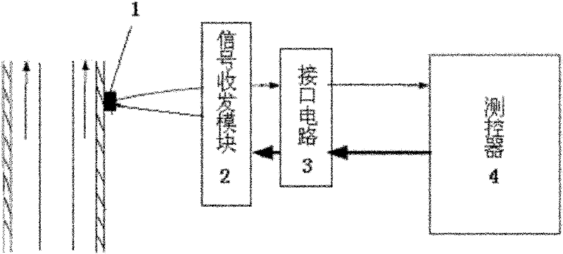
[0034] The device used in the present invention to measure the instantaneous flow in the annular space between the seabed riser and the drill string is an ultrasonic Doppler flowmeter. Such as figure 1 As shown, it includes an ultrasonic sensor 1, a signal transceiver module 2, an interface circuit 3, and a controller 4. The controller 4 communicates with the host computer, and the host computer completes tasks such as display, storage, and analysis of measurement data.

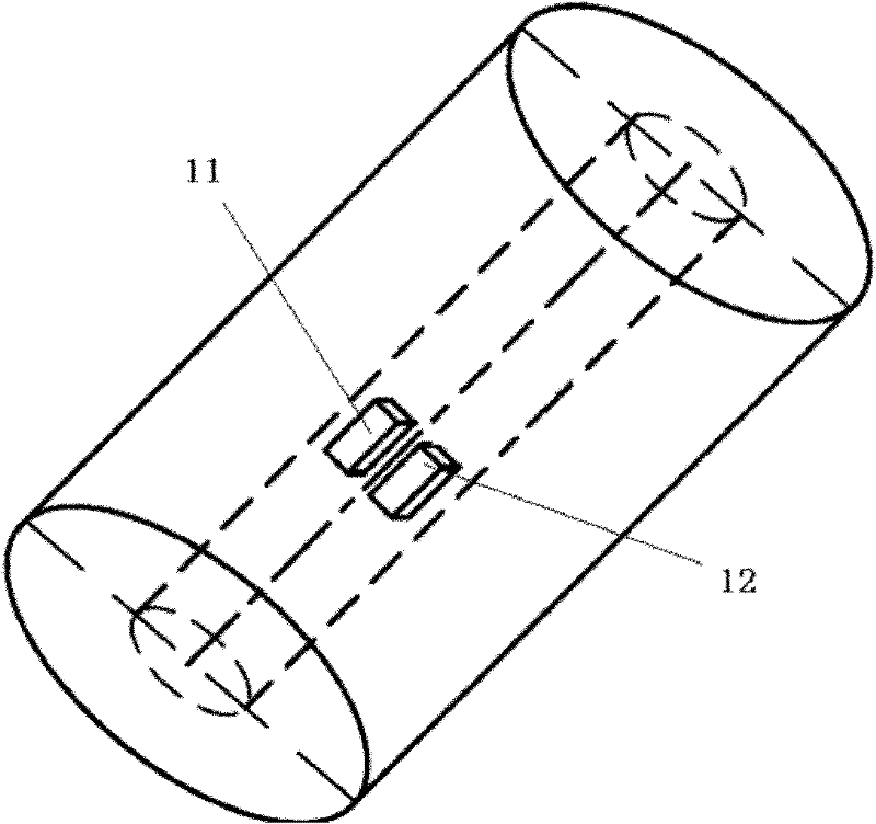
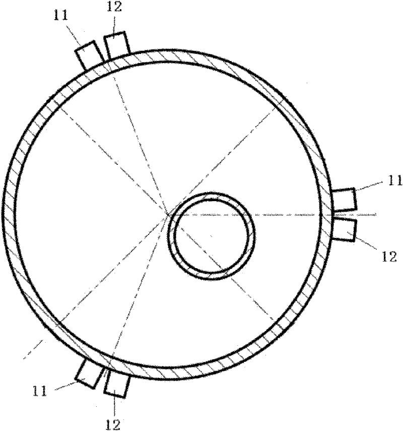
[0035] Such as figure 2 , 3 As shown, the ultrasonic sensor 1 is a pair or three pairs. Each pair of ultrasonic sensors 1 includes an ultrasonic transmitting sensor 11 and an ultrasonic receiving sensor 12, which are arranged side by side, clamped on the outer wall of the riser, and coated with a coupling agent between the riser and the riser. If there are three pairs of sensors...


PUM


Abstract

The invention relates to a device for measuring the annulus flow between a sea bottom marine riser and a drill column by using ultrasonic waves. The device comprises one pair or three pairs of ultrasonic wave sensors, a signal transceiving module, an interface circuit, a measurement and control device and an upper computer, wherein if three pairs of sensors are provided, the three pairs of sensors are arranged outside the marine riser and positioned on a certain cross section of the marine riser according to about 120-DEG phases, and a transmitting sensor and a receiving sensor in each pair of sensors are arranged in parallel and are connected with each other through the signal transceiving module and the interface circuit; one end of the measurement and control device is connected with the interface circuit and the upper computer; the measurement and control device comprises an amplifying circuit, a filter circuit, an automatic gain control circuit, an analog-to-digital converter, a voltage conversion circuit and a digital signal processor (DSP) which are sequentially connected with one another in an input-and-output sequence; and the output end of the DSP is sequentially connected with an analog-to-digital conversion circuit and a voltage adjustment circuit. In the device, measurement is finished by the Doppler effect, the annulus flow between the sea bottom marine riser and the drill column can be measured in real time, and the underground overflow condition is convenient to determine in time.

Description

technical field [0001] The invention relates to deepwater drilling monitoring equipment and methods, in particular to a device for measuring the instantaneous flow rate of the annular space between a seabed riser and a drill string. Background technique [0002] In the process of offshore deepwater drilling, the working environment of the submarine riser is harsh (deep water, high pressure, etc.), so the mechanical properties of the riser are highly required and the cost is high. A drill string is arranged inside the riser, but there is no method and device for measuring the instantaneous flow rate of the annular space between the riser and the drill string. [0003] At present, only the target flow meter is used to measure the outlet flow of drilling fluid. The measurement principle is to rely on the momentum of the drilling fluid at the outlet to change the position of the target body, and rely on the sensor to transmit the signal to measure the flow rate. The change resp...

Claims


Application Information

Patent Timeline
Patent Type & Authority Applications(China)
IPC IPC(8): E21B47/18G01F1/66
Inventor 姜伟蒋世全付建红周建良许亮斌何玉发张智刘飞赵辉
Owner CHINA NAT OFFSHORE OIL CORP
Why Eureka
Try Eureka