Line scanning differential confocal measuring device based on light path of pillar lens
What is AI technical title?
AI technical title is built by Patsnap AI team. It summarizes the technical point description of the patent document.
A differential confocal and measurement device technology, applied in the direction of measurement devices, optical devices, instruments, etc., can solve the problems of low measurement efficiency, achieve the effects of reducing measurement errors, uniform beam intensity distribution, and realizing three-dimensional measurement
Inactive Publication Date: 2012-11-28
HARBIN INST OF TECH
View PDF0 Cites 0 Cited by
Summary
Abstract
Description
Claims
Application Information
AI Technical Summary
This helps you quickly interpret patents by identifying the three key elements:
Problems solved by technology
Method used
Benefits of technology
Problems solved by technology
[0005] The purpose of the present invention is to solve the problem of low measurement efficiency when the differential confocal detection technology performs three-dimensional measurement, and to provide a line-scanning differential confocal measurement device based on the optical path of the cylindrical lens
Method used
Image
Click on the blue label to locate the original text in one second.
Reading with bidirectional positioning of images and text.
Examples
specific Embodiment approach 1
[0026] Specific implementation mode one: the following combination Figure 1 to Figure 3 To describe this embodiment,
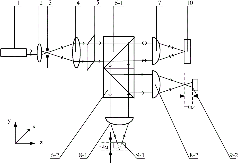
[0027] This embodiment includes a laser 1, a focusing lens 2, a pinhole 3, and a collimating beam expander lens 4 arranged in sequence on the coaxial optical path, and it also includes a rectangular diaphragm 5, a first beam splitter 6-1, and a second beam splitter 6-2. Detection focusing cylindrical lens 7, first collecting cylindrical lens 8-1, second collecting cylindrical lens 8-2, first linear array point detector 9-1 and second linear array point detector 9-2,
[0028] The laser beam generated by the laser 1 converges on the pinhole 3 through the focusing lens 2, and the point light source filtered by the pinhole 3 is expanded by the collimating beam expander lens 4, and then enters the first beam splitter 6- 1,
[0029] The transmitted light beam transmitted by the first beam splitter 6-1 is incident on the detection focusing cylindrical lens 7, and ...
specific Embodiment approach 2
[0036] Specific implementation mode two: the following combination figure 1 To describe this embodiment,
[0037] This embodiment is a further description of Embodiment 1, and the pinhole 3 is arranged at the focal point of the image side of the focusing lens 2 . Others are the same as the first embodiment.
specific Embodiment approach 3
[0038] Specific implementation mode three: the following combination figure 1 To describe this embodiment,
[0039] This embodiment is a further description of Embodiment 1 or 2. The focus on the image side of the focusing lens 2 coincides with the focus on the object side of the collimator and beam expander lens 4 . Others are the same as the first or second embodiment.
PUM
Abstract
The invention relates to a line scanning differential confocal measuring device based on a light path of a pillar lens, belonging to the field of a microcosmic measurement technique. The line scanning differential confocal measuring device provided by the invention can be used for solving the problem of low measurement efficiency when the three-dimensional measurement is carried out by a differential confocal detection technique. In the line scanning differential confocal measuring device provided by the invention, laser beams generated by a laser device are gathered in a pinhole through a focusing lens, expanded through a collimation and beam expansion lens after being filtered and then emitted to a first spectroscope through a rectangular diaphragm; the transmitted light beams of the first spectroscope are emitted to a detection focusing pillar lens; the line focusing is formed on the image focusing plane of the detection focusing pillar lens; after the light beams which are reflected by a sample to be measured are transmitted through the detection focusing pillar lens, the light beams which pass through the first spectroscope are emitted to a second spectroscope; and after passing through a first collecting pillar lens, the transmitted light beams of the second spectroscope are subjected to line focusing to reach the photosensitive surface of a first linear array point detector. The line scanning differential confocal measuring device provided by the invention is suitable for differential confocal detection.
Description
technical field [0001] The invention relates to a line-scanning differential confocal measuring device based on a cylindrical lens optical path, and belongs to the technical field of microscopic measurement. Background technique [0002] The basic idea of confocal microscopy imaging technology is to suppress stray light by introducing a pinhole detector and generate axial tomography capability. This technology obtains the current X-Y surface image by performing two-dimensional scanning measurement on the X-Y surface of the sample point by point. Then scan the sample in the Z direction (axial direction), and point-by-point two-dimensional scanning on the next X-Y plane, and so on, by "stacking" the obtained two-dimensional images to obtain the three-dimensional reconstructed image of the sample. Because this measurement method is very time-consuming, in order to improve the measurement efficiency of confocal detection technology, a method of using slit detection instead of ...
Claims
Application Information
Patent Timeline
Application Date:The date an application was filed.
Publication Date:The date a patent or application was officially published.
First Publication Date:The earliest publication date of a patent with the same application number.
Issue Date:Publication date of the patent grant document.
PCT Entry Date:The Entry date of PCT National Phase.
Estimated Expiry Date:The statutory expiry date of a patent right according to the Patent Law, and it is the longest term of protection that the patent right can achieve without the termination of the patent right due to other reasons(Term extension factor has been taken into account ).
Invalid Date:Actual expiry date is based on effective date or publication date of legal transaction data of invalid patent.

