
Quasi-distributed sensor network based on time division multiplex and matched optical fiber grating technology

A fiber grating and sensor network technology, applied in the direction of reducing unwanted effects, can solve the problems of insufficient sensing accuracy, low reflectivity, and different reflectivity, and achieve the effect of matching the high speed of the grating

Inactive Publication Date: 2011-09-07
SOUTHWEST JIAOTONG UNIV
View PDF10 Cites 19 Cited by
  • Summary
  • Abstract
  • Description
  • Claims
  • Application Information

AI Technical Summary

Problems solved by technology

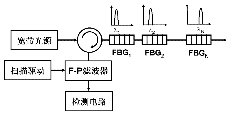
Using edge filters to demodulate the intensity of the central reflection wavelength variation of fiber gratings can avoid the limitation of mechanical devices, but usually only one fiber grating can be accommodated in the same fiber, and it is impossible to use one fiber to connect multiple gratings in series for quasi-distribution measurement
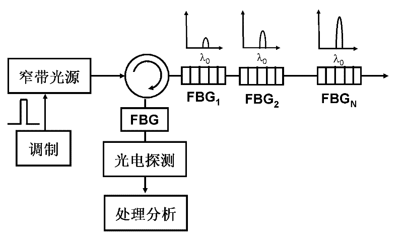
On the other hand, some technologies are also based on time-division multiplexing technology, but they can only use the modulated pulse sequence of a narrow-band light source to enter the sensing grating sequence, and all sensing fiber gratings can only use the same center due to the limited bandwidth of the light source. wavelength but different reflectivity (generally the reflectivity near the light source is lower and increases one by one) for time domain analysis (such as figure 2 As shown, the central wavelength of the grating is the same, but the reflectivity is different)
Such a solution mainly has the problems of large crosstalk between different reflection points and insufficient sensing accuracy.

Method used


Image

  • Quasi-distributed sensor network based on time division multiplex and matched optical fiber grating technology
  • Quasi-distributed sensor network based on time division multiplex and matched optical fiber grating technology
  • Quasi-distributed sensor network based on time division multiplex and matched optical fiber grating technology

Examples


Embodiment Construction

[0019] The present invention will be further described below in conjunction with the accompanying drawings.

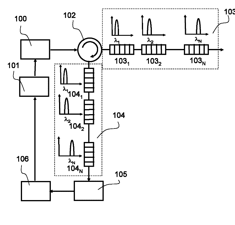
[0020] Such as image 3 As shown, the broadband light source 100 is directly modulated by the narrow pulse sequence signal 101, and then enters the sensing fiber grating sequence after passing through the optical circulator 102 (an isolator can also be added between the light source 100 and the optical circulator 102 to further improve the protection of the light source) 103. The central reflection wavelengths of each grating in the sensing fiber grating sequence are different, so that the broadband optical pulse will be reflected back by each fiber grating; the reflected light will enter the matching optical fiber with edge filtering function after passing through the optical circulator 102 again The grating sequence 104 performs edge filtering on the reflected light respectively; the light pulse after the edge filtering reaches the photodetector 105 for photoelectric...


PUM


Abstract

The invention discloses a quasi-distributed sensor network based on time division multiplex and matched optical fiber grating technology, which can accommodate a plurality of groups of optical fiber grating pairs with matched central reflection wavelength in a grating sensor network. A broadband light source is directly modulated in high speed by a narrow pulse signal sequence, a light pulse emitted by the broadband light source passes through an isolator and a circulator to enter into a sensing optical fiber grating and a matched optical fiber grating sequence, the light pulse is reflected back to light pulse sequences of different time delays with variation of the position of the optical fiber grating in the transmission process, and the light pulse sequences are processed with photoelectric conversion by a photoelectric detector to form electric pulse signal sequences. Arrangement position of the pulse sequence on a time domain is relative to spatial position of the optical fiber grating in the sensor network, wherein the optical fiber grating forms reflection, so that the signal is processed based on a high speed circuit, different gratings are distinguished according to a relation of time and position of the pulse signal, and wavelength change of each sensing grating is respectively obtained according to peak intensity of the pulse signal.

Description

technical field [0001] The invention relates to the technical field of a method for measuring environmental parameters such as pressure, strain or temperature by using time division multiplexing and matching grating in the field of fiber grating measurement or sensing. Background technique [0002] Fiber Bragg Grating (or Fiber Bragg Grating, Fiber Bragg Grating - FBG) is currently a hot spot in the research and application of fiber optic sensing. Fiber Bragg Grating sensors have the advantages of anti-electromagnetic interference, high precision, long effective service life, strong wavelength coding multiplexing ability, etc., and have been widely used in the field of sensing in recent years. [0003] One of the outstanding advantages of fiber grating sensors is that it can realize quasi-distributed sensing, that is, engrave multiple fiber gratings on one or more optical fibers, and use multiplexing technology to realize quasi-distributed sensing of various sensing quantiti...

Claims


Application Information

Patent Timeline
Patent Type & Authority Applications(China)
IPC IPC(8): G01D3/028
Inventor 闫连山张兆亭潘炜罗斌周国华张志勇易安林温坤华王圣根
Owner SOUTHWEST JIAOTONG UNIV
Learn More