
Device heating method

A heating method and marking device technology, applied in the direction of temperature control using electric methods, can solve the problems of unpredictable and controllable heating effects, inability to adjust the heating mechanism by itself, and rapid instantaneous temperature changes, etc.

Inactive Publication Date: 2011-09-07
MITAC PRECISION TECH(KUNSHAN) CORP
View PDF4 Cites 17 Cited by
  • Summary
  • Abstract
  • Description
  • Claims
  • Application Information

AI Technical Summary

Problems solved by technology

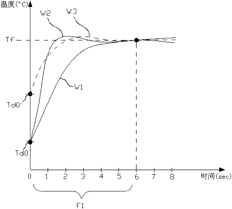
[0007] When the initial temperature Td0' of the device is different, because the existing heating technology uses ordinary heating power to heat, the temperature curve W3 shows that it has already been heated to the target temperature Tf before the predetermined heating time course F1, resulting in an instantaneous overheating situation
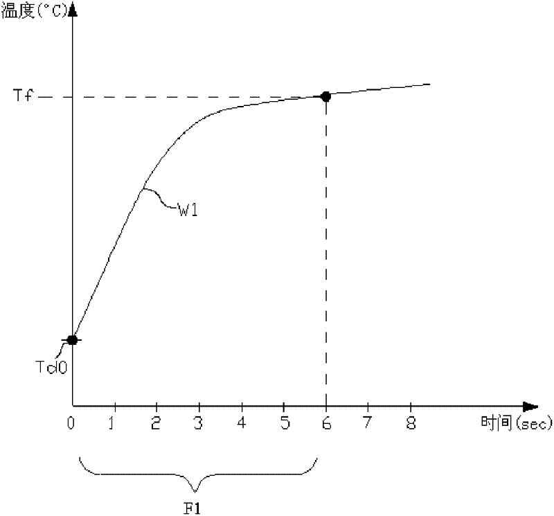
[0008] In view of the above, when using the existing heating technology to heat a certain device, there will be problems such as uneven temperature rise rate, excessive instantaneous temperature change and uncontrollable heating time.
For devices with heat-sensitive characteristics, the heating mechanism cannot be adjusted by itself
In addition, once the heater changes the heating source, the characteristic resistance of the heating medium changes, or uses a heater to heat different devices, the temperature curve will also change greatly, and the heating effect cannot be predicted and controlled.

Method used


Image

  • Device heating method
  • Device heating method
  • Device heating method

Examples


Embodiment Construction

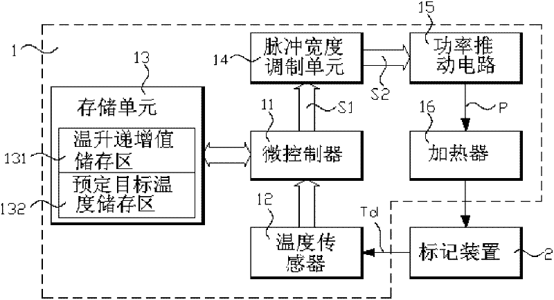
[0021] refer to image 3 As shown, it shows a circuit block diagram of a preferred embodiment of the present invention. As shown in the figure, the heating module 1 includes a microcontroller (microcontroller) 11, and the microcontroller 11 is respectively connected to a temperature sensor 12, a storage unit 13, and a pulse width modulation (Pulse Width Modulation, PWM) unit 14 and A power boost circuit 15 is connected to a heater 16 . One of the main applications of the heating module 1 and the marking device 2 of the present invention is a portable electronic device, such as a notebook computer. The microcontroller 11 can be an embedded controller equipped with a keyboard controller, and the marking device 2 can be a hard disk. In addition to the pulse width modulation unit 14 , a digital-to-analog circuit (digital-to-analog circuit) can also be used to drive the heater 16 .

[0022] The temperature sensor 12 is used to sense the device temperature Td of a marking device ...


PUM


Abstract

The invention discloses a device heating method. A marking device is heated to a target temperature by a plurality of temperature ranges. The method comprises the following steps of: sensing the current device temperature of the marking device; comparing the current device temperature with range set temperature in a current temperature rang to obtain a stage error value; regulating heating power according to the stage error value; heating the marking device with the heating power; progressively rising the range set temperature in the current temperature range by using a preset temperature progressive rising value to obtain the range set temperature of the next temperature range; and repeating the same steps in each temperature range until the range set temperature or device temperature reaches the target temperature.

Description

【Technical field】 [0001] The present invention relates to the design of a heating method, in particular to a device heating method. 【Background technique】 [0002] If an electronic device (such as a notebook computer) needs to start or operate in a low temperature environment, a heater (such as a hard disk heater) is required to heat a specific hardware module (such as a hard disk). However, the current heaters, whether they are controlled by hardware circuits or application software or firmware, are simply heated with a fixed heating power, or heated at different temperatures with different heating powers. [0003] refer to figure 1 As shown, the temperature curve W1 represents the relationship between the temperature and time of the heated device when the existing heating technology is used for heating. The existing heating technology only considers the target temperature Tf to be heated to by the device, and does not consider the temperature change at each time point du...

Claims


Application Information

Patent Timeline
Patent Type & Authority Applications(China)
IPC IPC(8): G05D23/19
Inventor 游世豪
Owner MITAC PRECISION TECH(KUNSHAN) CORP
Learn More