Drive device

A driving device and drive shaft technology, which is applied in transportation and packaging, vehicle cleaning, vehicle maintenance, etc., can solve the problems of large installation space, flexible use and other problems, and achieve the effect of long output shaft length

Inactive Publication Date: 2011-09-07
ROBERT BOSCH GMBH
View PDF1 Cites 0 Cited by
  • Summary
  • Abstract
  • Description
  • Claims
  • Application Information

AI Technical Summary

Problems solved by technology

It has proven to be a disadvantage here that the large worm gear and the resulting oscillating movement of the push rod require a large installation space, which makes flexible use difficult in different vehicle models

Method used


Image

  • Drive device
  • Drive device
  • Drive device

Examples


Embodiment Construction

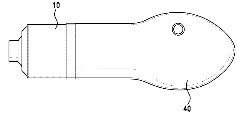
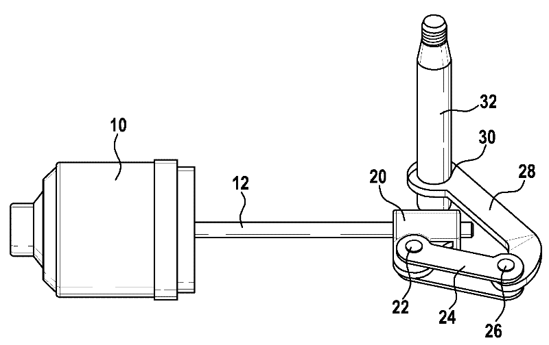
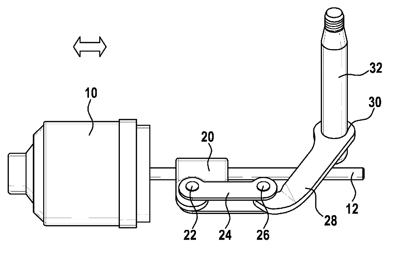
[0019] exist Figures 1a to 1c The drive according to the invention of the wiper device is shown for moving the output shaft 32 . In this case, the motor 10 preferably reversibly drives a rotatably mounted drive shaft 12 , which is preferably designed as a screw or worm thread. The drive shaft 12 is connected to the linear motion element 20 in a non-rotatable manner, so that the rotational motion of the drive shaft 12 can be converted into the linear motion of the linear motion element 20 . The linear movement element 20 is connected via a first hinge 22 to a connecting rod 24 , wherein the connecting rod 24 is connected via a second hinge 26 to a rocker arm 28 and the rocker arm 28 is connected non-rotatably to an output shaft 32 via a hollow hole 30 . The linear motion element 20 is driven by the motor 10 via the drive shaft 12 and moves back and forth on the drive shaft 12 between the motor 10 and the drive shaft 32 ( Figure 1a to Figure 1c ). In this case, the linear m...


PUM


Abstract

The invention relates to a drive device for a windshield wiper device for moving an output shaft (32), having an input shaft (12) which can be driven through a motor (10) and which is connected to a linear motion element (20) in a rotationally fixed manner, wherein the linear motion element (20) is connected to the output shaft (32) through exactly one coupler (24) and exactly one rocker (28), wherein the coupler (24) is supported between the linear motion element (20) and the rocker (28) in an articulated manner and the rocker (28) is connected to the output shaft (32) in a rotationally fixed manner. In said manner, large forces can be transmitted using self-locking in a small design.

Description

technical field [0001] The invention relates to a drive for a windshield wiper device and to a windshield wiper device for a motor vehicle. Background technique [0002] In motor vehicles with large windshields with reversingly operating wiper systems, two-motor wiper systems are generally used, wherein essentially reversible motors are used with conventional guide rods between the oscillating motor and output shaft. For example, DE 10 2006 042 322 A1 discloses a wiper device with a wiper drive and a transmission for driving the wiper shaft, wherein a swinging rotational movement is generated in the wiper shaft by the fact that the worm is arranged as a push rod, The push rod is connected to the worm gear via an eccentric and articulated connection. A disadvantage here has been that the bulky worm gear and the resulting oscillating movement of the push rod require a large installation space, which makes flexible use in different vehicle models difficult. Contents of the i...

Claims


Application Information

Patent Timeline
Patent Type & Authority Applications(China)
IPC IPC(8): B60S1/18B60S1/24
CPCB60S1/166B60S1/245Y10T74/18928
Inventor S.迈尔J-M.里特
Owner ROBERT BOSCH GMBH
Why Eureka
Try Eureka