
Dry pump

A technology of dry pumps and pump chambers, applied in the field of volume transfer dry pumps, which can solve the problems of reduced exhaust efficiency, temperature difference, deformation and expansion of dry pumps, etc., and achieve the goals of improving exhaust efficiency, eliminating temperature imbalance, and efficient cooling Effect

Active Publication Date: 2011-09-07
ULVAC INC
View PDF7 Cites 0 Cited by
  • Summary
  • Abstract
  • Description
  • Claims
  • Application Information

AI Technical Summary

Problems solved by technology

As in the past, the structure that uniformly cools the entire pump body with a refrigerant etc. creates a temperature difference between the pump chambers, making it impossible to maintain a uniform temperature throughout the dry pump.
When a temperature deviation occurs inside the dry pump, there is a problem that the exhaust efficiency decreases due to local deformation and expansion of the dry pump.

Method used


Image

  • Dry pump
  • Dry pump
  • Dry pump

Examples


Embodiment

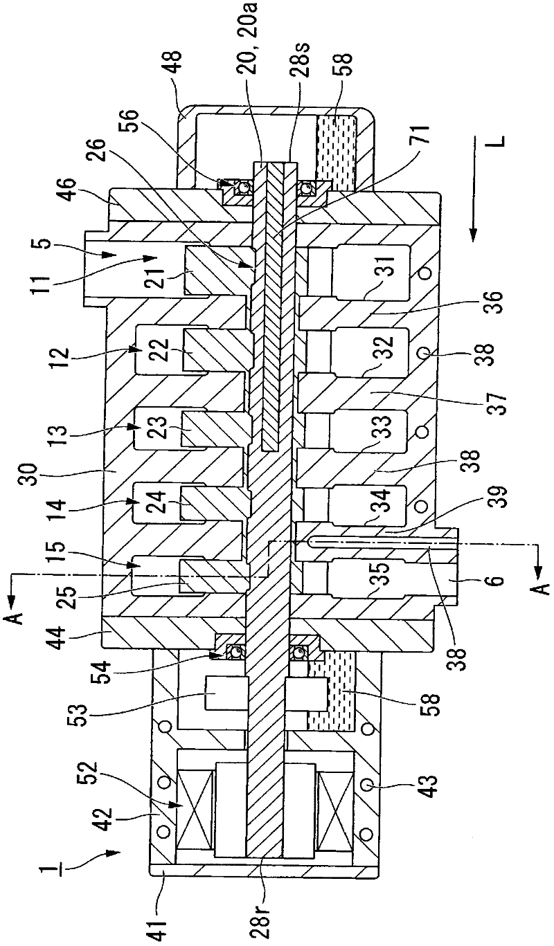
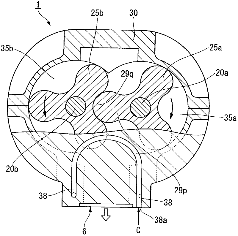
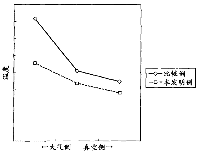
[0042] Examples for verifying the effects of the present invention are shown below. use as figure 1 , 2 The shown dry pump in which the refrigerant passage 35 is formed inside the partition wall 39 to cool the fifth-stage pump chamber 15 on the atmospheric side (discharge side) is an example of the present invention. In addition, as a comparative example, a conventional dry pump in which no refrigerant passage is particularly formed in the partition wall defining the pump chamber on the atmospheric side (discharge side) was used.


PUM


Abstract

A dry pump comprising cylinders (31, 32, 33, 34, 35), pump chambers (11, 12, 13, 14, 15) respectively formed in the cylinders(31, 32, 33, 34, 35), partition walls (36, 37, 38, 39) each separating adjacent pump chambers (11, 12, 13, 14, 15) from each other, rotors (21, 22, 23, 24, 25) contained inside the pump chambers(11, 12, 13, 14, 15), rotor shafts(20a, 20b) which are the rotating shafts of the rotors (21, 22, 23, 24, 25), and refrigerant paths (38) formed inside the partition walls (36, 37, 38, 39) and allowing a refrigerant to flow therethrough.

Description

technical field [0001] This invention relates to volumetric displacement dry pumps. [0002] this application claims priority based on Japanese Patent Application No. 2008-263938 for which it applied on October 10, 2008, and uses the content here. Background technique [0003] A dry pump is used for exhaust. A dry pump has a pump chamber in which a rotor is accommodated in a pump body. A dry pump rotates a rotor in a pump body to compress and move exhaust gas, thereby decompressing and exhausting a closed space provided at a suction port (for example, refer to Patent Document 1). In particular, when exhausting to obtain a moderate vacuum or a good vacuum, a multistage dry pump is used in which a plurality of pump chambers are connected in series from an exhaust gas suction port to a discharge port (for example, refer to Patent Document 2). [0004] When the dry pump is running, the exhaust gas is compressed in the pump chamber to generate heat, and the temperature of the ...

Claims


Application Information

Patent Timeline
Patent Type & Authority Applications(China)
IPC IPC(8): F04C29/04F04C25/02
CPCF04C29/04F04C23/001F04C2240/30F04C25/02F01C21/104F04C18/123F04C2/18
Inventor 铃木敏生
Owner ULVAC INC
Learn More