Imaging optical device

A technology of optical device and lens driving device, which is applied in the direction of optics, projection device, printing device, etc., can solve problems such as hand shaking, and achieve the effect of preventing plastic deformation

Inactive Publication Date: 2011-09-07
SANKYO SEIKI MFG CO LTD
View PDF5 Cites 34 Cited by
  • Summary
  • Abstract
  • Description
  • Claims
  • Application Information

AI Technical Summary

Problems solved by technology

In the case of using mobile devices, hand shake is prone to occur when taking pictures

Method used


Image

  • Imaging optical device
  • Imaging optical device
  • Imaging optical device

Examples


Embodiment approach 1

[0074] (The overall structure of the optical device for photography)

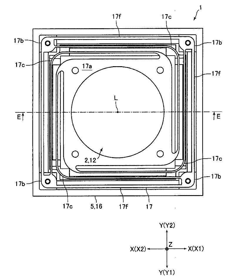
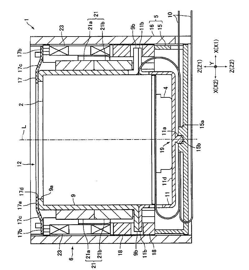
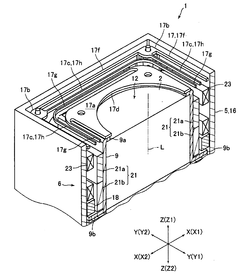
[0075] figure 1 It is a plan view of the imaging optical device 1 according to Embodiment 1 of the present invention. figure 2 Yes figure 1 Cutaway view of the E-E section. image 3 yes means figure 1 A perspective view of a part of the structure in the E-E section.

[0076] In the description below, if Figure 1 ~ Figure 3 As shown, the three directions orthogonal to each other are respectively referred to as the X direction, the Y direction, and the Z direction. Additionally, the Figure 1 ~ Figure 3 Take the X1 direction side as the "right" side, the X2 direction side as the "left" side, the Y1 direction side as the "front" side, the Y2 direction side as the "rear (rear)" side, and the Z1 direction side as the "upper" side. ” side, and the side in the Z2 direction is taken as the “lower” side.

[0077] The imaging optical device 1 of the present embodiment is a small and thin video camera instal...

Embodiment approach 2

[0130] (The overall structure of the optical device for photography)

[0131] Image 6 It is a cross-sectional view of the imaging optical device 31 according to Embodiment 2 of the present invention. In the following description, the same reference numerals are assigned to the same configurations as in Embodiment 1, and descriptions thereof are omitted or simplified. In addition, in the following description, as in Embodiment 1, the three directions perpendicular to each other are referred to as the X direction, the Y direction, and the Z direction, respectively, and the side in the X1 direction is referred to as the "right" side, and the side in the X2 direction is referred to as the "right" side. For the left side, the side in the Y1 direction is referred to as the "front" side, the side in the Y2 direction is referred to as the "rear (rear)" side, the side in the Z1 direction is referred to as the "upper" side, and the side in the Z2 direction is referred to as the "downw...

Embodiment approach 3

[0162] Figure 8 It is a sectional view of the photographing optical device 51 according to Embodiment 3 of the present invention. Figure 9 Yes Figure 8 A top view of the leaf spring 67 is shown. In the following description, the same reference numerals are assigned to the same configurations as in Embodiments 1 and 2, and descriptions thereof are omitted or simplified. In addition, in the following description, as in Embodiments 1 and 2, the three directions perpendicular to each other are respectively referred to as the X direction, the Y direction, and the Z direction, and the X1 direction side is referred to as the "right" side, and the X2 direction side is referred to as the "right" side. As the "left" side, let the Y1 direction side be the "front" side, the Y2 direction side be the "rear (rear)" side, the Z1 direction side be the "upper" side, and the Z2 direction side be the "lower" side.

[0163] The photographing optical device 51 of the present embodiment is a s...


PUM


Abstract

An imaging optical device configured such that shaking can be appropriately corrected by smoothly rocking a lens drive device on which a lens and an imaging element are mounted. An imaging optical device (1) comprises: a movable module (12) having a lens drive device (2) on which a lens and an imaging element are mounted; a support body (5) for supporting the movable module (12); a rocking drive mechanism for rocking the movable module (12); and a plate spring (17) for rockably supporting the movable module (12). The plate spring (17) is provided with a holding section (17a) for holding the movable module (12), a fixed section (17b) fixed to the support body (5), and a spring section (17c) for connecting the holding section (17a) and the fixed section (17b) to each other. The spring section (17c) can deform in the direction perpendicular to the optical axis (L) and in the direction of the optical axis.

Description

technical field [0001] The present invention relates to a photographic optical device having a shake correction function capable of swinging a lens driving device equipped with a lens and an imaging element to correct shake. Background technique [0002] In recent years, mobile devices such as mobile phones have been equipped with optical devices for photographing. In the case of using a mobile device, hand shake is prone to occur when taking pictures. Therefore, an optical device capable of correcting hand shake during photography has been proposed (for example, refer to Patent Document 1). [0003] The optical device described in this patent document 1 includes: a movable part equipped with a lens and an imaging element; a pivot fixed to the base of the optical device and contacting the bottom surface of the movable part; a leaf spring for swingably supporting the movable part; and a swing mechanism for swinging the movable part. In this optical device, the swing mechan...

Claims


Application Information

Patent Timeline
Patent Type & Authority Applications(China)
IPC IPC(8): G03B5/00F16F1/26
CPCH04N5/2254G03B5/02G03B5/00G03B5/04H04N5/2257H04N5/2253H04N23/54H04N23/57H04N23/55
Inventor 南泽伸司唐泽敏行武居勇一武田正长田章弘石原久宽宫崎清史柳泽克重
Owner SANKYO SEIKI MFG CO LTD
Why Eureka
Try Eureka