Thick-wall pipe hydroforming device

An internal high-pressure forming and thick-walled pipe technology is applied in the field of pipe forming devices and internal high-pressure forming devices for thick-walled stepped pipes. It can solve the problem of high pressure sealing, reduce the cost of the mold, and reduce the high stress area.

Inactive Publication Date: 2011-09-14
XI AN JIAOTONG UNIV
View PDF5 Cites 15 Cited by
  • Summary
  • Abstract
  • Description
  • Claims
  • Application Information

AI Technical Summary

Problems solved by technology

[0005] The purpose of the present invention is to overcome the above-mentioned shortcomings of the prior art, and provide a thick-walled pipe internal high-pressure forming device. High, difficult sealing at both ends of the pipe and low forming accuracy

Method used


Image

  • Thick-wall pipe hydroforming device
  • Thick-wall pipe hydroforming device
  • Thick-wall pipe hydroforming device

Examples


Embodiment 1

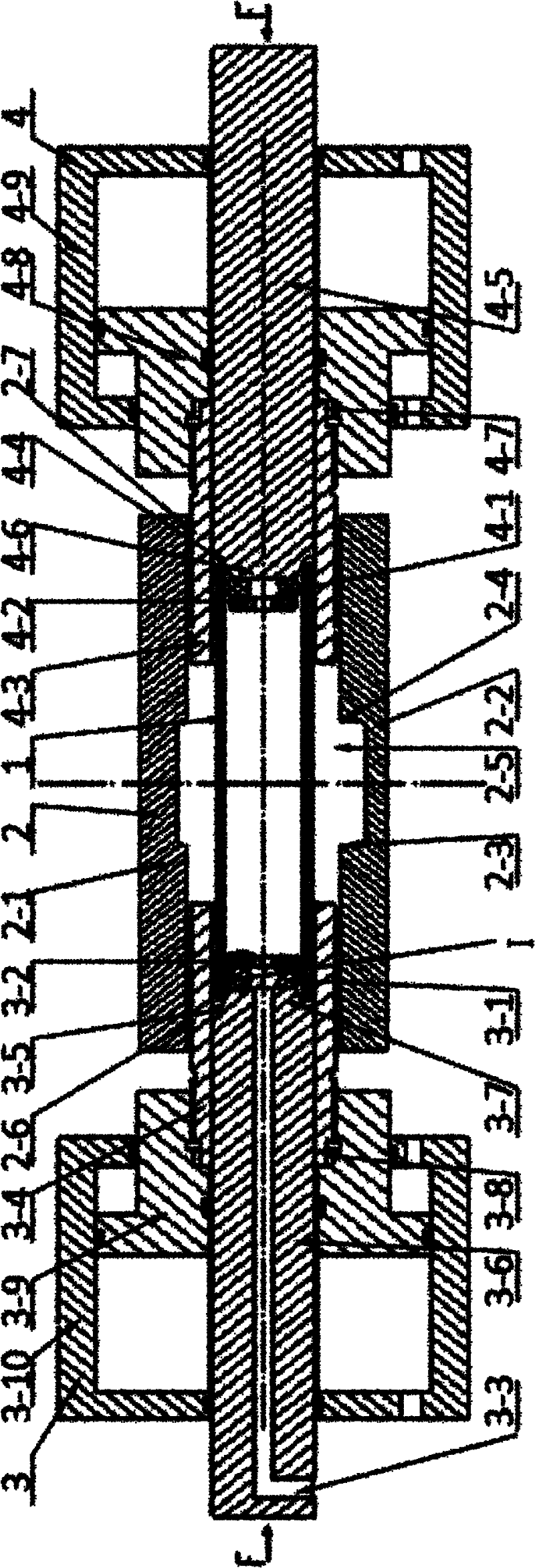
[0031] see figure 1 and Figure 6, the main body mold 2 is composed of an upper main body mold 2-1 and a lower main body mold 2-2, and the upper main body mold 2-1 and the lower main body mold 2-2 jointly form a molding cavity 2-5, and the left end of the main body mold is provided with a The left guide hole 2-6 communicated with the cavity 2-5, the right end is provided with the right guide hole 2-7 communicated with the cavity 2-5, the main body mold 2 is installed on the vertical press in the traditional way, and the left feed device 3 is provided with There are left punch 3-6, left additional hydraulic cylinder body 3-10, left additional hydraulic cylinder piston rod 3-9, left moving mold 3-4, left sealing ring 3-1, left gasket 3-2, right The feeding device 4 is provided with a right punch 4-5, a right additional hydraulic cylinder body 4-9, a right additional hydraulic cylinder piston rod 4-8, a right movable mold 4-3, a right sealing ring 4-1, and a right gasket 4 -2, ...

Embodiment 2

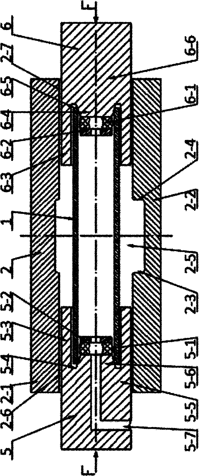
[0035] see figure 2 , the present embodiment is also based on the above-mentioned basic structure of the present invention, and its main difference from Embodiment 1 is: the left feeding device (such as figure 2 5) left moving mold (such as figure 2 5-3 in) and the left punch (such as figure 2 5-5) is made into one, the right feeding device (such as figure 2 6) of the right moving mold (such as figure 2 6-3) and the right punch (such as figure 2 6-6) is made into one, left moving mold (such as figure 2 5-3 in) and the left punch (such as figure 2 5-5) is installed on the horizontal press on the left side of the main mold 2, thereby eliminating the left additional hydraulic cylinder, and the right moving mold (such as figure 2 6-3 in) and the right punch (such as figure 2 6-6) is installed on the horizontal press on the right side of the main body mold 2, thereby saving the right additional hydraulic cylinder. After the device and the tube blank are fixed, wh...


PUM

PropertyMeasurementUnit
angleaaaaaaaaaa

Abstract

The invention discloses a thick-wall pipe hydroforming device. The thick-wall pipe hydroforming device comprises a main body module and a left feed device and a right feed device which are arranged at two ends of the main body module respectively; the main body module consists of an upper main body module and a lower main body module, and after the upper main body module and the lower main body module are closed, the main body module has a cylindrical structure with two open ends, and a cavity is formed in the main body module; the left end of the main body module is provided with a left guide hole which is communicated with the cavity, and the right end of the main body module is provided with a right guide hole which is communicated with the cavity; the right end of a left movable module is arranged in the left guide hole; the outer cylinder side wall of a left punch is in clearance fit with the left movable module; the left end of a right movable module is arranged in the right guide hole; and the outer circular side wall of a right punch is in clearance fit with the right movable module. By giving a certain initial gap to the movable module and the main body module, the high contact pressure area acting on the main body module by the movable module is reduced, the frictional resistance applied to the guide area is reduced, the axial feeding of a pipe is facilitated, and the quality of the hydroformed workpiece of a thick-wall pipe is improved. Meanwhile, due to the adoption of a self-sealing structure of a pipe end, the high pressure sealing problem can be solved.

Description

technical field [0001] The invention belongs to the technical field of pipe processing equipment, and relates to a pipe forming device, in particular to an internal high-pressure forming device for thick-walled stepped pipes. Background technique [0002] Hydroforming, also known as hydroforming, is a kind of liquid as the pressure transmission medium, which uses controllable internal high pressure (working pressure up to 400-600MPa) to deform the metal blank into Modern plastic processing techniques for parts with complex 3D shapes. Internal high pressure forming of pipes is a process in which the metal pipes are subjected to high-pressure fluid inside, forcing the pipes to bulge and deform outwards to obtain the desired shape. Therefore, internal high pressure can easily form complex components with three-dimensional curves and special-shaped cross-sections. Compared with other traditional forming processes, the formed parts have the characteristics of high strength, stro...

Claims


Application Information

Patent Timeline
Patent Type & Authority Applications(China)
IPC IPC(8): B21D26/047B21D26/035
Inventor 张琦吴春冬赵升吨陈余秋
Owner XI AN JIAOTONG UNIV
Why Eureka
Try Eureka