Synchronous humidifying wet spinning device

A technology of humidifying device and pressurizing device, which is applied in the direction of textile and papermaking, continuous winding spinning machine, spinning machine, etc. It can solve the problems that ring spinning hairiness level cannot meet the requirements and spinning hairiness is too much, etc. Achieve the effect of easy promotion, less hairiness and simple structure

Active Publication Date: 2011-09-14
XINJIANG YIDA TEXTILE +1
View PDF8 Cites 10 Cited by
  • Summary
  • Abstract
  • Description
  • Claims
  • Application Information

AI Technical Summary

Problems solved by technology

However, this device has the problem of too much hairiness in the spun yarn. In order to solve this problem, an airflow negative pressure gathering system or a mechanical gathering system is added to the ring spinning device. The airflow negative pressure gathering system passes through the holed roller or The grid ring gathers the strand fibers under the action of the airflow, and the mechanical gathering system gathers the strand fibers through the ceramic channel with magnets
The airflow negative pressure compacting system or mechanical compacting system mentioned above can reduce yarn hairiness to a certain extent, but with the improvement of the process and the further increase of customer requirements, the hairiness level of the existing ring spinning can no longer meet the requirements. New solutions had to be developed

Method used


Image

  • Synchronous humidifying wet spinning device
  • Synchronous humidifying wet spinning device
  • Synchronous humidifying wet spinning device

Examples


Embodiment

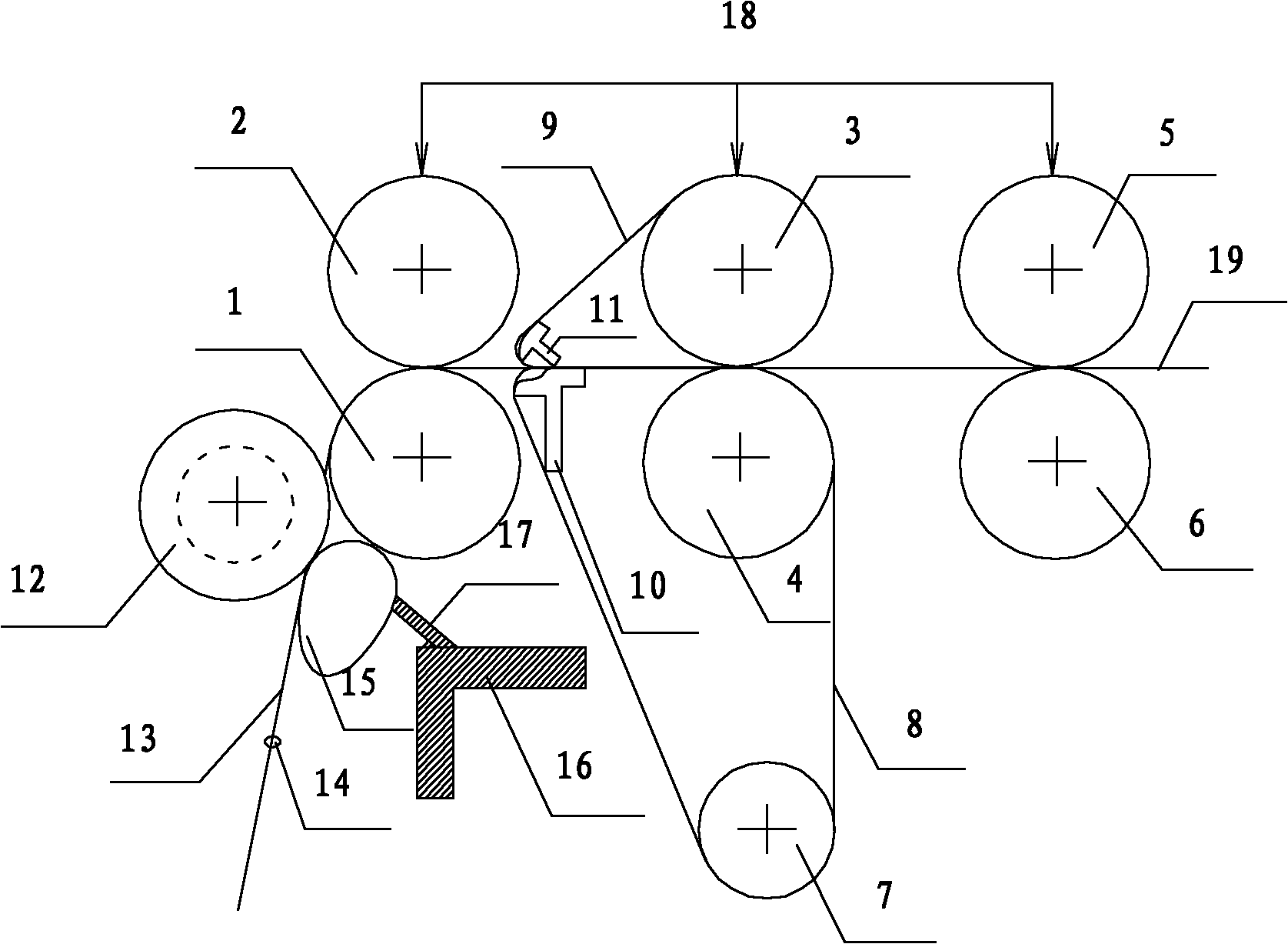
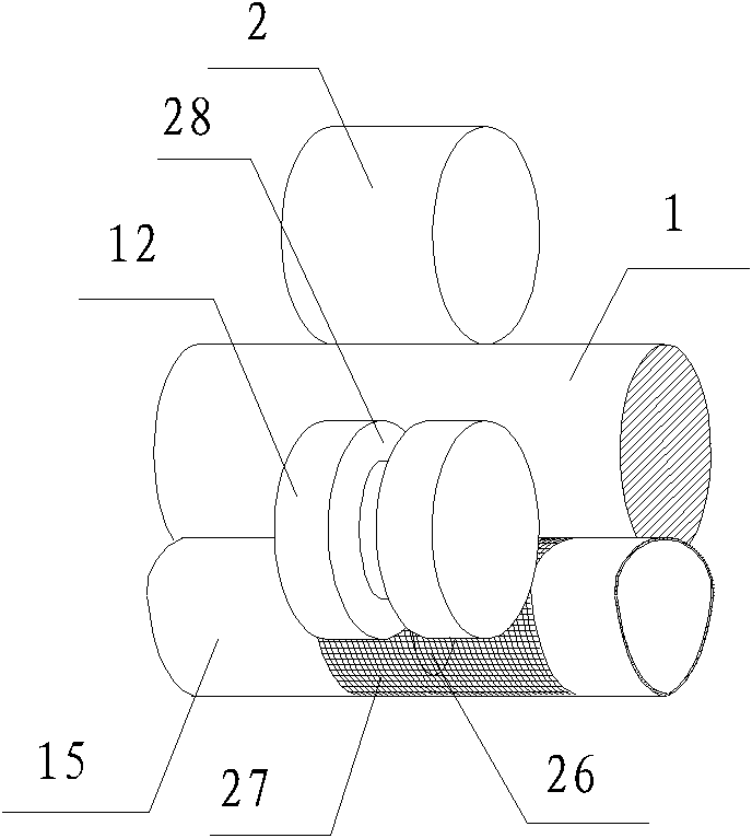
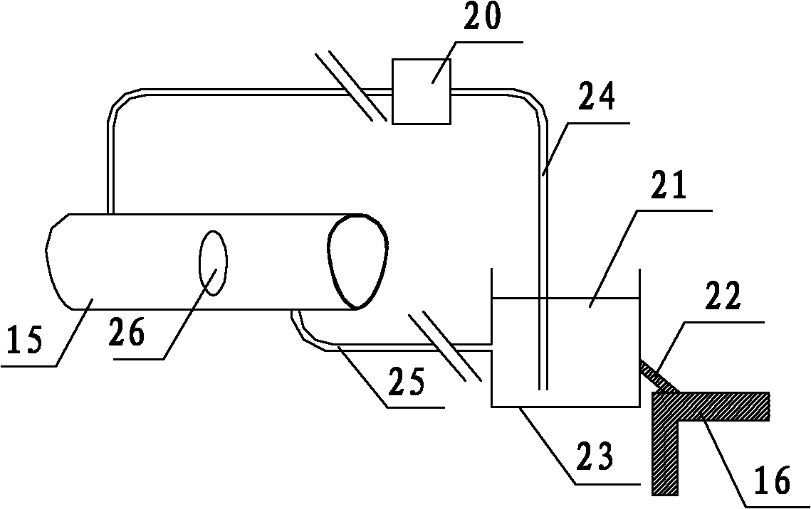
[0019] refer to Figure 1-4 , a synchronously humidified wet spinning device, comprising a front top roller 2, a front bottom roller 1, a middle top roller 3, a middle bottom roller 4, an upper short apron 9, a lower pin 10, Three-roller double-apron drafting mechanism consisting of upper pin 11, lower long apron 8, tension roller 7, rear upper top roller 5, rear lower roller 6, and pressurizing device 18, and roving 19 from rear upper top roller 5 and rear lower roller 6, and is pulled out by the yarn guide hook 14 between the front top roller 2 and the front bottom roller 1. A synchronous humidifying mechanism is provided between the front bottom roller 1 and the guide hook 14. The synchronous humidifying mechanism consists of a grooved roller 12 with a groove 26, a hollow special-shaped tube 15 with a humidification hole 26, and can rotate around the special-shaped tube 15. The grid ring 27, humidification tank 23, water pump 20, liquid inlet pipe 24 and liquid return pipe...

Embodiment 1

[0028] Embodiment 1 of the present invention: adopt the wet spinning device of the present invention to spin 80 British count pure cotton yarns;

Embodiment 2

[0029] Embodiment 2 of the present invention: Spinning 40 lbs. 65 / 35 cotton / viscose blended yarn with the wet spinning device of the present invention.


PUM

PropertyMeasurementUnit
thicknessaaaaaaaaaa

Abstract

The invention discloses a synchronous humidifying wet spinning device, which comprises a front lower roller, a front upper leather roller, a guide wire and a pressurization device which are all arranged on a frame. A synchronous humidifying mechanism is arranged between the front lower roller and the guide wire. The synchronous humidifying mechanism comprises a groove roller with a groove, a hollow shaped tube with a humidifying hole, a grid ring capable of rotating around the shaped tube and a humidifying device, wherein the groove on the groove roller corresponds to the humidifying hole; the front upper leather roller drives the groove roller to synchronously rotate; the groove roller drives the grid ring and the front lower roller to synchronously rotate; and the humidifying device is used for outputting humidifying liquid to the humidifying hole. The synchronous humidifying wet spinning device has the advantages that the raw materials have good adaptability; spun yarns with less fuzz and more uniform evenness can be produced from any short fiber ring spinning yarn raw materials which are being spun; the synchronous humidifying wet spinning device has the characteristics of simple structure, stability and reliability in operation, convenience for reconstruction on the original spinning frame, low cost and easiness in popularization; and the requirement for sustainable production is met.

Description

technical field [0001] The invention belongs to the field of textiles, in particular to a ring spinning wet spinning device. Background technique [0002] The ring spinning device is the current mainstream spinning device and has a wide range of applications. However, this device has the problem of too much hairiness in the spun yarn. In order to solve this problem, an airflow negative pressure gathering system or a mechanical gathering system is added to the ring spinning device, wherein the airflow negative pressure gathering system passes through the holed roller or The grid ring gathers the strand fibers under the action of the airflow, and the mechanical gathering system gathers the strand fibers through the ceramic channel with magnets. The airflow negative pressure compacting system or mechanical compacting system mentioned above can reduce yarn hairiness to a certain extent, but with the improvement of the process and the further increase of customer requirements, t...

Claims


Application Information

Patent Timeline
Patent Type & Authority Applications(China)
IPC IPC(8): D01H13/30D01H1/02D01H13/02
Inventor 何小东刘霞宋均燕赵阳张玉高徐念祖王少明王照旭李刚高强李光海曹维民
Owner XINJIANG YIDA TEXTILE
Why Eureka
Try Eureka