Supercharge Your Innovation With Domain-Expert AI Agents!

Fault diagnosis device and method for high-pressure common-rail fuel injection system

A technology of a fuel injection system and a fault diagnosis device, which is applied to a fuel injection device, a measuring device, a charging system, etc., can solve the problems of high software overhead, damage to the engine mechanical structure, and increased software workload, and achieves a simple hardware circuit. , The effect of comprehensive fault types and reliable fault diagnosis

Inactive Publication Date: 2012-07-25
ZHEJIANG UNIV
View PDF1 Cites 0 Cited by
  • Summary
  • Abstract
  • Description
  • Claims
  • Application Information

AI Technical Summary

Problems solved by technology

However, a large proportion of the faults of electronically controlled diesel engines come from the faults of sensors and actuators, and this method cannot specify the specific fault location
Moreover, the software overhead is large, the working environment of the common rail system is complex, and the increase in software workload will inevitably increase the difficulty of control
On the other hand, the fault diagnosis is not comprehensive
First of all, this method misses the fault detection of another main actuator of the high-pressure common rail—the high-pressure oil pump.
Secondly, the types of faults diagnosed are incomplete, and they are all diagnosed after the fault occurs, which has no preventive effect at all.
If a failure occurs, it is likely to cause damage to the hardware circuit of the diesel engine electronic control unit or damage to the mechanical structure of the engine

Method used


Image

  • Fault diagnosis device and method for high-pressure common-rail fuel injection system
  • Fault diagnosis device and method for high-pressure common-rail fuel injection system
  • Fault diagnosis device and method for high-pressure common-rail fuel injection system

Examples


Embodiment Construction

[0021] The specific implementation and working principle of the high-pressure oil pump solenoid valve and fuel injector fault diagnosis solution of the present invention will be described in detail below in conjunction with the accompanying drawings.

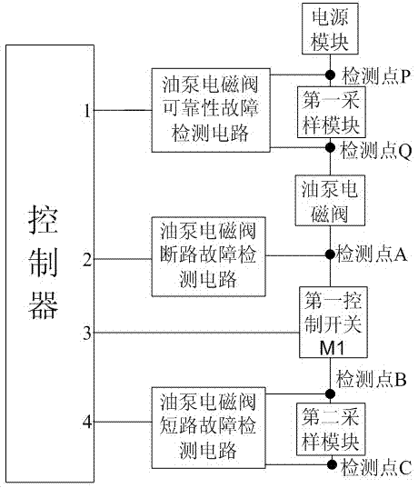
[0022] Such as figure 1As shown, the internal module connection relationship of the oil pump solenoid valve fault detection device is: the controller pin 1 is connected to the oil pump solenoid valve reliability fault detection circuit, and the oil pump solenoid valve reliability fault detection circuit is connected to the detection point P and detection point Q. The detection point P and detection point Q are connected to both ends of the first sampling module, the controller pin 2 is connected to the oil pump solenoid valve open circuit fault detection circuit, the oil pump solenoid valve open circuit fault detection circuit is connected to the detection point A, and the controller pin 3 is connected to the The first control s...


PUM


Abstract

The invention discloses a fault diagnosis device and method for a high-pressure common-rail fuel injection system. Before the oil pump magnetic valve operates, the controller can read the diagnosis feedback signal of an oil pump magnetic valve fault diagnosis device and determine whether the magnetic valve has an open-circuit fault; when the magnetic valve operates, the controller can read the corresponding signal and determine whether a short-circuit fault and a reliability fault occur; before the fuel injector starts actuation, the controller can read the diagnosis feedback signal of the injector and determine whether the fuel injector is subjected to short-circuit fault to earth; then the low end switch is turned on, the controller can read the signal once again and determine whether the open-circuit fault appears; when the injector starts operating, the controller can read the corresponding signal and determine whether the inside short-circuit fault and the reliability fault appear. The fault diagnosis device and method can provide corresponding protections when the oil pump and the injector break down and can protect the engine and the electronic control system thereof. The hardware circuit device is simple and effective and the software cost is low, thus, the reliability of high-pressure common-rail electronic control system can be improved.

Description

technical field [0001] The invention relates to a fault diagnosis device and method for a high-pressure common rail fuel injection system. Background technique [0002] Most of the existing electronically controlled diesel engine fuel injection systems have fuel injection system fault diagnosis devices. Chinese patent CN1773101 discloses a method for diagnosing a fuel injector failure of a high-pressure common rail fuel injection system for a diesel engine. A software method is used to judge the failure of the mechanical system of the fuel injector of the fuel injection system. This method first uses the crankshaft sensor to measure the difference in the instantaneous speed of each cylinder of the engine, and uses the diagnostic software to determine the faulty cylinder based on the compensation algorithm for the balanced fuel injection amount between the engine cylinders, and then according to the change rule of the common rail cavity pressure measured by the common rail pr...

Claims


Application Information

Patent Timeline
Patent Type & Authority Patents(China)
IPC IPC(8): F02M65/00
Inventor 周文华密刚刚沈成宇简辉黄啸臧润涛
Owner ZHEJIANG UNIV
Features
  • R&D
  • Intellectual Property
  • Life Sciences
  • Materials
  • Tech Scout
  • Unparalleled Data Quality
  • Higher Quality Content
  • 60% Fewer Hallucinations
Learn More