Double-speed oil cylinder

A technology of oil cylinder and oil cylinder back cover, which is applied in the direction of fluid pressure actuating device, etc., which can solve the problems of low operating time of more than 30 seconds, no double-speed function, and unsatisfactory speed, so as to improve operating efficiency and reduce Effect of hydraulic loss and compact structure

Inactive Publication Date: 2011-09-14
JIASHAN SUPERPOWER TOOLS
View PDF6 Cites 10 Cited by
  • Summary
  • Abstract
  • Description
  • Claims
  • Application Information

AI Technical Summary

Problems solved by technology

Some larger wood splitters in the prior art all use double pumps, that is, when the load is light, the double pumps work at the same time to generate a large flow to supply the oil cylinder to obtain a faster speed, but when the load is heavy, the double pumps are large. The pump is automatically in the unloading state, only the small pump works under high pressure and makes the oil cylinder generate a huge thrust. This function is achieved by changing the hydraulic flow of the system. Still in the unloading state and not working, the large flow generated by it always produces some unnecessary energy loss. At the same time, the flow of these larger log splitters is already quite large, but their speed is still not ideal. It takes more than 15 seconds for one operation ; and some small wood splitters do not have a double-speed function due to various reasons such as cost, and their operating efficiency is extremely low, and the operating time for one operation needs to be more than 30 seconds

Method used


Image

  • Double-speed oil cylinder
  • Double-speed oil cylinder
  • Double-speed oil cylinder

Examples


Embodiment 1

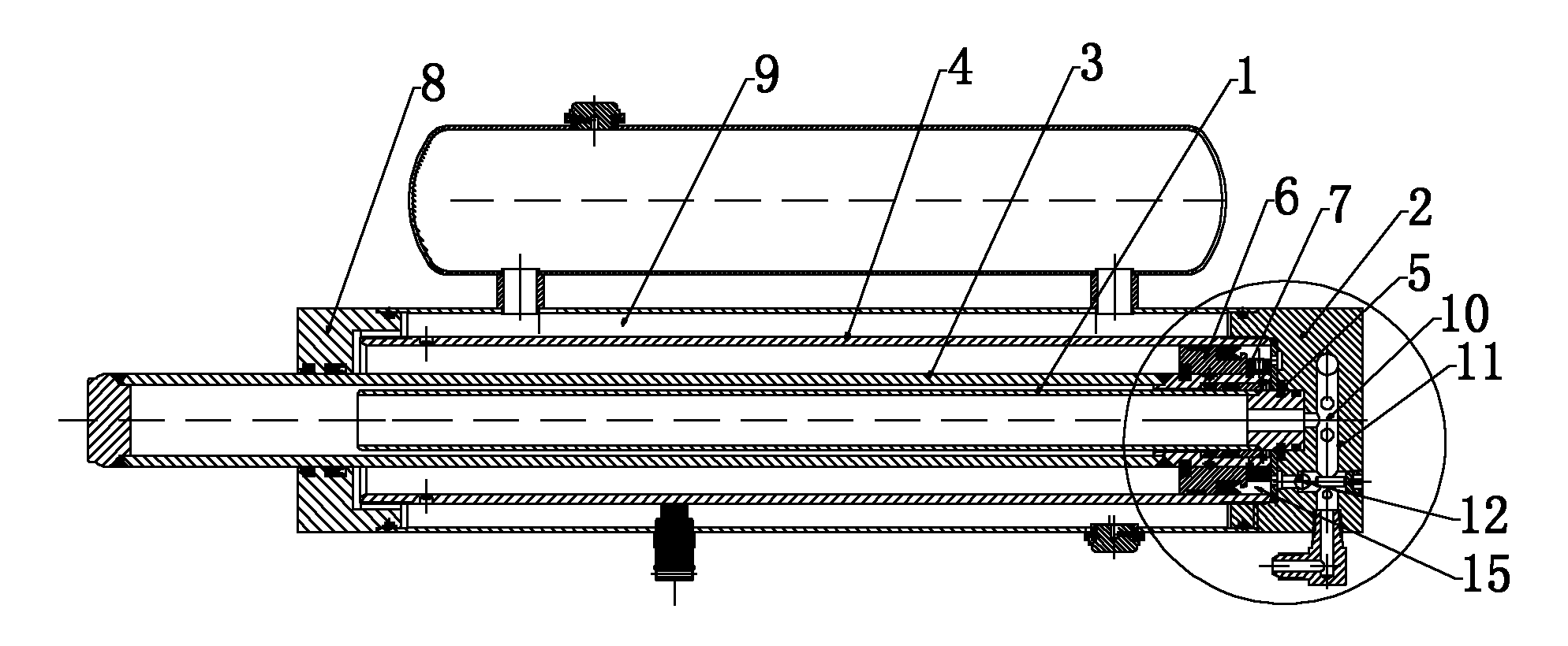
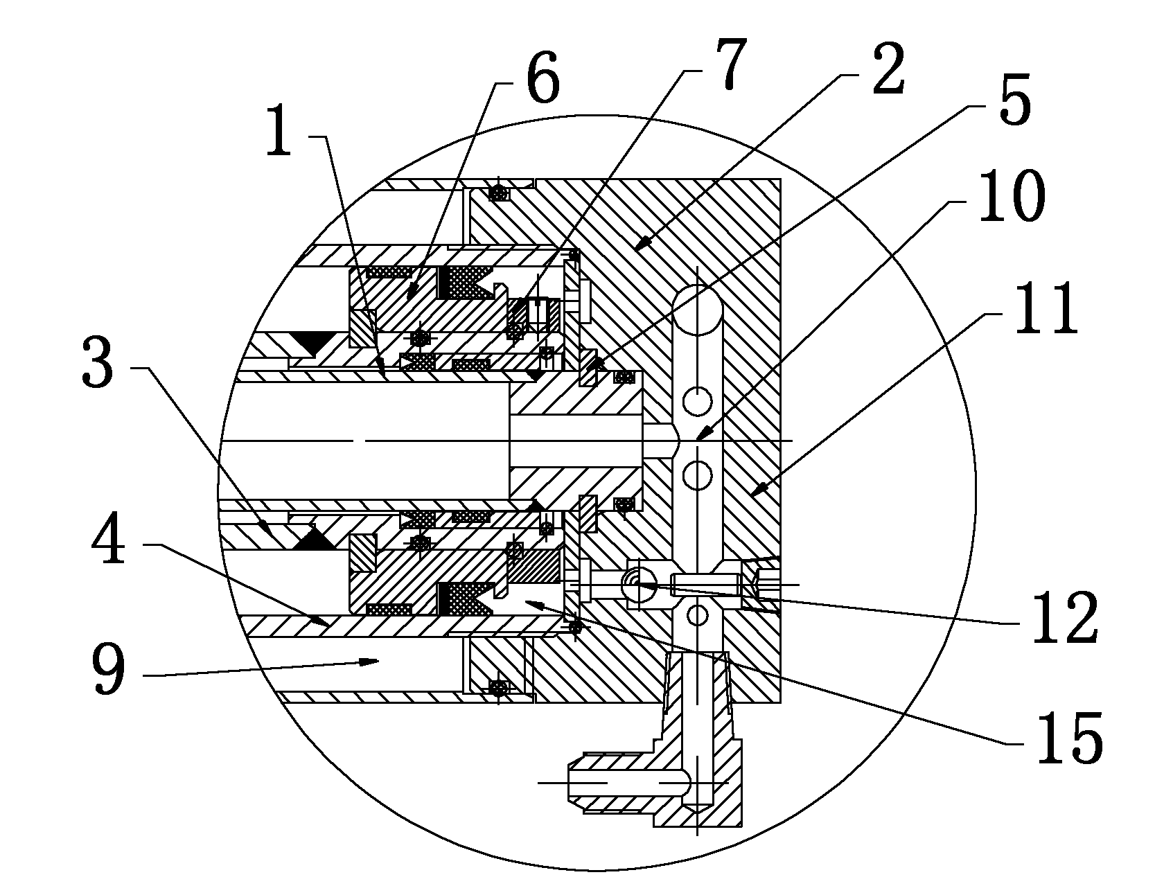
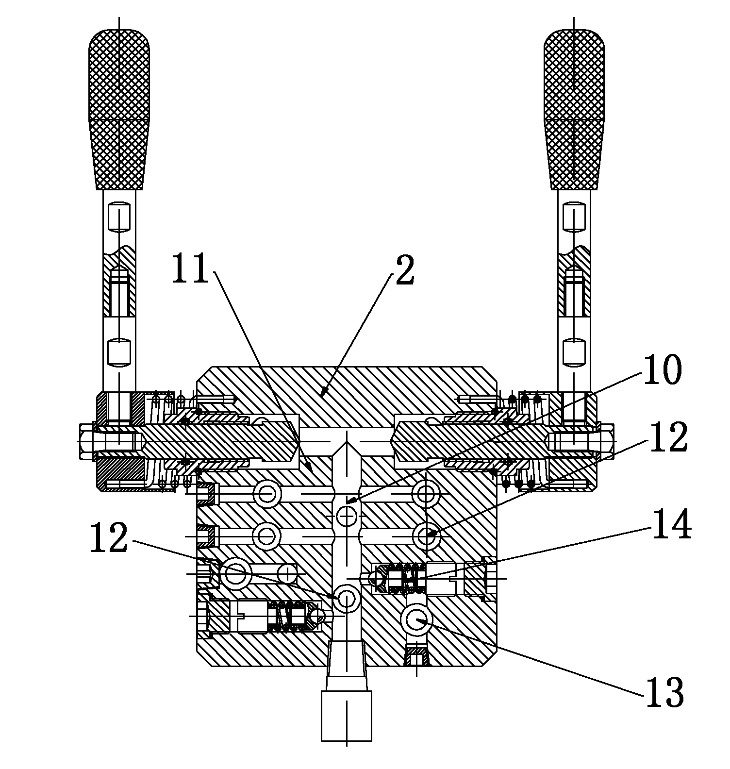
[0015] Such as figure 1 , figure 2 , image 3 , Figure 4 As shown, the two-speed oil cylinder described in this embodiment mainly includes a cylinder block 4, an oil cylinder front cover 8, an oil cylinder rear cover 2, a large piston 6, a fixed piston rod 1 and a moving piston rod 3, and one end of the cylinder body 4 passes through the back of the oil cylinder. The cover 2 is closed, and the other end of the cylinder body 4 forms a sealed space through the front cover 8 of the oil cylinder and the moving piston rod 3. The large piston 6 is arranged at one end of the moving piston rod 3. There is a fixed piston rod 1, the fixed piston rod 1 is a hollow structure with both ends connected, one end of the fixed piston rod 1 is connected with the oil cylinder rear cover 2, and the end of the movable piston rod 3 in the cylinder body 4 is connected to the fixed piston rod 1 through the large piston 6 The outer wall is closed, and the large piston 6 is slidably connected on th...


PUM


Abstract

The invention discloses a double-speed oil cylinder, mainly comprising a cylinder body, an oil cylinder front cover, an oil cylinder back cover, a large piston and a movable piston rod, wherein the other end of the cylinder body and the movable piston rod form a sealed space by the oil cylinder front cover, the large piston is arranged at one end of the movable piston rod, the movable piston rod is of a hollow structure, a fixed piston rod is arranged in the movable piston rod, the fixed piston rod is of a hollow structure, two ends of the fixed piston rod are communicated, one end of the fixed piston rod is connected with the oil cylinder back cover, one end of the movable piston rod in the cylinder body is sealed with the outer wall of the fixed piston rod by the large piston, and the large piston is glidingly connected onto the fixed piston rod. In the double-speed oil cylinder, a pushing force can be changed by means of the different compression areas of the movable piston rod and the large piston, synchronously the pushing speed and the retreating speed of the oil cylinder can be improved when the smaller compression area is used; therefore, the wood splitting speed can be greatly improved and the working efficiency is improved. A sequence adjusting valve is arranged so that the switching between the fast push and the large pushing force can be automatically realized aiming at requirements on the pushing force; and therefore, the operation is more simple and convenient.

Description

technical field [0001] The invention relates to the field of oil cylinders, in particular to a two-speed oil cylinder for wood splitters. Background technique [0002] There are many types of wood splitters, including manual, pneumatic, electric, and motorized. They are widely used in the garden wood industry in Europe, America and Australia. Wood is a very environmentally friendly organic energy source. These countries advocate the use of wood for heating and cooking. Therefore, all farms and even every household use log splitters; at present, domestic and foreign log splitters are usually composed of power units, control valves, executive cylinders and racks. Most of the executive cylinders are single-stage single-acting or double-acting hydraulic cylinders. In order to shorten the length of the wood splitter, a double-acting two-stage oil cylinder is occasionally seen. The operation of the log splitter requires the cylinder to generate a huge thrust when it starts to spl...

Claims


Application Information

Patent Timeline
Patent Type & Authority Applications(China)
IPC IPC(8): F15B15/17
Inventor 吕玉新彭忠诚胡松甫
Owner JIASHAN SUPERPOWER TOOLS
Why Eureka
Try Eureka