
Self-locking nut

A technology of self-locking nuts and nuts, which is applied in the direction of nuts, locking fasteners, screws, etc., can solve the problems of increased processing costs, insufficient locking force, and stress concentration in grooves, so as to improve production efficiency and stress Uniform, avoid stress concentration effect

Inactive Publication Date: 2011-09-14
浙江环达紧固件有限公司 +1
View PDF6 Cites 3 Cited by
  • Summary
  • Abstract
  • Description
  • Claims
  • Application Information

AI Technical Summary

Problems solved by technology

[0003] Usually in engineering, double nuts are used to fasten the nuts to prevent loosening, but the double nuts are only the thickening of the single nut, and cannot really play the role of locking and preventing loosening
[0004] Other existing self-locking nuts are often equipped with other accessories, such as slots and pins or steel balls, to locate the stuck nut, which will cause operation on the nut, or the nut is added with a spring washer, and the deformation of the spring washer Insufficient locking force is insufficient, or grooves are processed on the end face of the nut, and stress concentration is easily formed at the groove, causing cracks or cracks
At the same time, the increase of accessories will also make the use method complicated, increase the labor intensity of workers, and increase the processing cost
[0005] The fastening nut specified by the current national standard is a shell nut stamped from a steel sheet. Although this kind of nut saves material and is convenient to manufacture, it is very easy to install the nut in reverse due to the uneven technical level of the workers. It has a self-locking effect. At the same time, the materials on the market are uneven, and the locking effect is also uneven. The thin sheet material also leads to insufficient strength of this kind of nut.

Method used


Image

  • Self-locking nut
  • Self-locking nut

Examples


Embodiment Construction

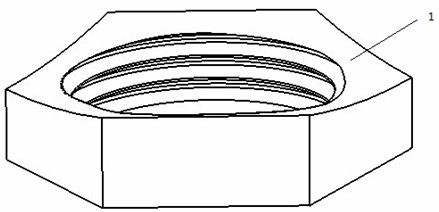
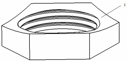
[0011] Such as figure 1 As mentioned above, the self-locking nut includes a nut 1, the edge of the nut is polygonal, and the upper and lower end surfaces of the nut are concave curved surfaces.

[0012] The concave curved surface is a surface of revolution, the center of which is located on the axis of the screw hole of the self-locking nut, and the surface of revolution is a cylindrical surface, a spherical surface or a hyperboloid. The polygonal edges are regular hexagons or regular quadrilaterals. The polygonal edges are regular hexagons. The material of the self-locking nut is spring steel or tool steel. The spring steel is 65Mn.

[0013] The regular hexagonal nut edge can unify the tools during installation, reduce the number of tools, reduce production costs and improve production efficiency. The upper and lower ends of the nut are symmetrical concave cylindrical surfaces to facilitate processing, uniform deformation, and reduce the stress concentration of the self-l...


PUM


Abstract

The invention discloses a self-locking nut which comprises a nut. The edge of the nut is polygonal, and the upper end surface and the lower end surface of the nut are concave curved surfaces which are revolution surfaces; the revolution center of the revolution surface is positioned on the axis of a screw hole of a self-locking nut, and the revolution surface can be a cylindrical surface, a spherical surface or a double-curved surface; the edge of the polygon is a regular hexagon or a regular quadrangle; the self-locking nut is made of spring steel or tool steel; and the spring steel is 65Mn. The self-locking nut can be locked by the elastic deformation of the nut without affiliated accessories, so that the self-locking nut is convenient to use, preferably adopts symmetrical curved surfaces as two end surfaces, can realize the function of locking by frontal and reverse installation, has no requirement on the engineering level of workers, and enables the stress on the self-locking nut to be uniform so as to avoid the concentration of stress.

Description

technical field [0001] The invention relates to an engineering nut, in particular to a self-locking nut. Background technique [0002] As a commonly used fastener, bolts and nuts are widely used in various fields. If the nut is installed for a long time, it will loosen due to the vibration or movement of the fastener. [0003] Usually in engineering, double nuts are used to fasten the nuts to prevent loosening, but the double nuts are only the thickening of the single nut, and cannot really play the role of locking and preventing loosening. [0004] Other existing self-locking nuts are often equipped with other accessories, such as slots and pins or steel balls, to locate the stuck nut, which will cause operation on the nut, or the nut is added with a spring washer, and the deformation of the spring washer Insufficient locking force is insufficient, or grooves are processed on the end face of the nut, and stress concentration is easily formed at the groove, causing cracks ...

Claims


Application Information

Patent Timeline
Patent Type & Authority Applications(China)
IPC IPC(8): F16B39/284F16B37/00
Inventor 邱玉清胡树根赖霞虹李阳
Owner 浙江环达紧固件有限公司
Learn More