Small sample hydraulic burst test method and device for material property test

A test method and hydraulic technology, applied in the direction of applying stable tension/pressure to test the strength of materials, etc., can solve the problems of complex stress state, difficult control, and difficult theoretical analysis of small wafer samples, and achieve simplified loading uncertainty. the effect of simplifying the stress situation

Inactive Publication Date: 2011-09-14
CHINA SPECIAL EQUIP INSPECTION & RES INST +1
View PDF3 Cites 17 Cited by
  • Summary
  • Abstract
  • Description
  • Claims
  • Application Information

AI Technical Summary

Problems solved by technology

[0007] However, the force state of the small disc sample during the small punch test is complicated, and it is difficult to conduct effective theoretical analysis to obtain an analytical solution. Therefore, the research mainly focuses on the data accumulation of the test, and on the basis of the data accumulation, the small punch can be obtained. Empirical formulas relating bar test results to material mechanical properties, as well as simulating the test process through finite element calculations, and interpreting the data with various assumptions
However, because the small punch test is extremely sensitive to the processing method of the sample, the surface condition, the centering degree of the punch, the aperture diameter of the lower fixture platform and other factors, and the above factors are difficult to control during the test preparation and execution process, the obtained The data contains differences caused by too many out-of-control factors, resulting in the reliability of the small punch test cannot be effectively guaranteed

Method used


Image

  • Small sample hydraulic burst test method and device for material property test
  • Small sample hydraulic burst test method and device for material property test
  • Small sample hydraulic burst test method and device for material property test

Examples


Embodiment approach 1

[0034] The sample hydraulic bursting test method proposed in the embodiment of the present invention comprises the steps of:

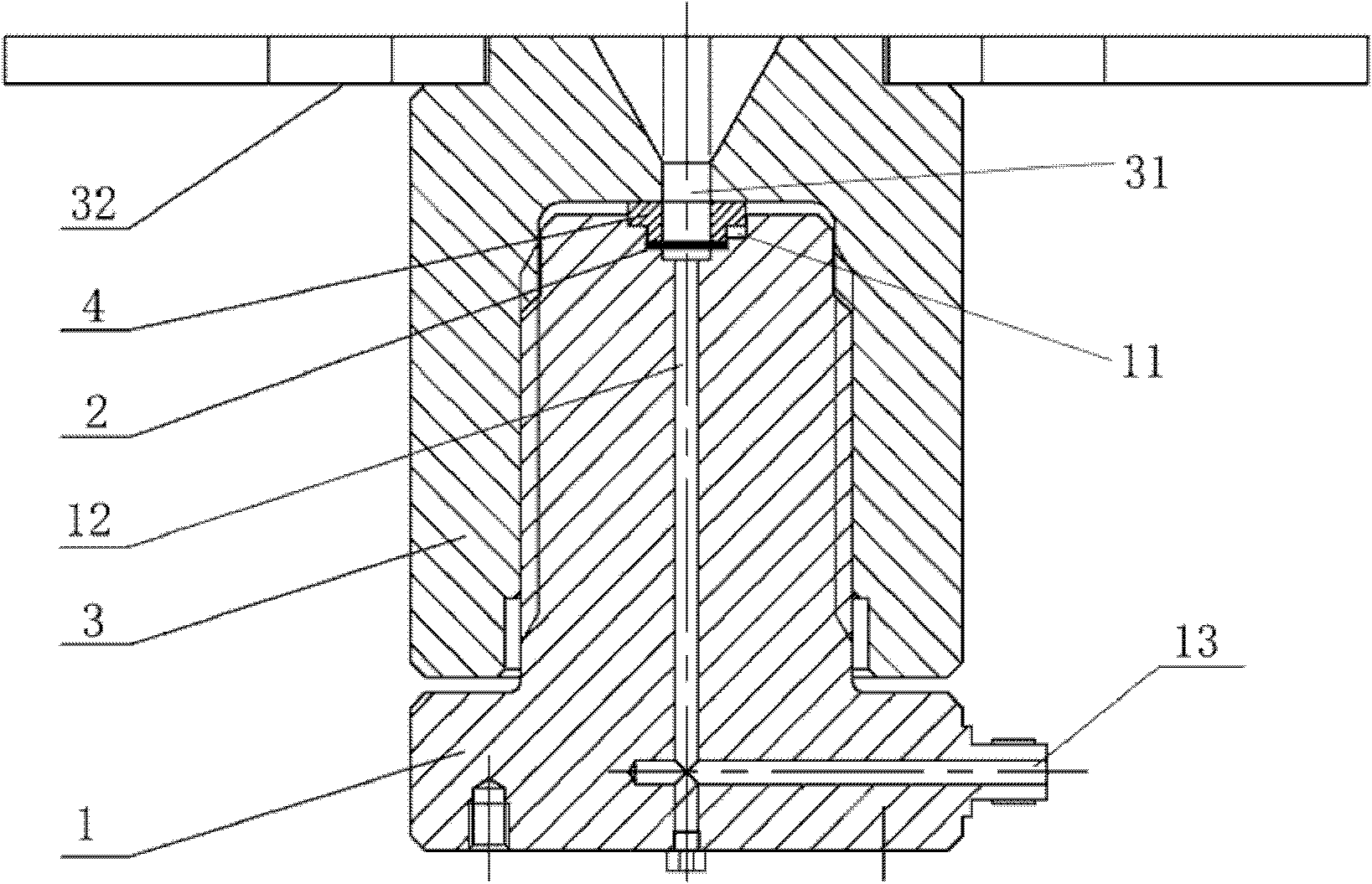
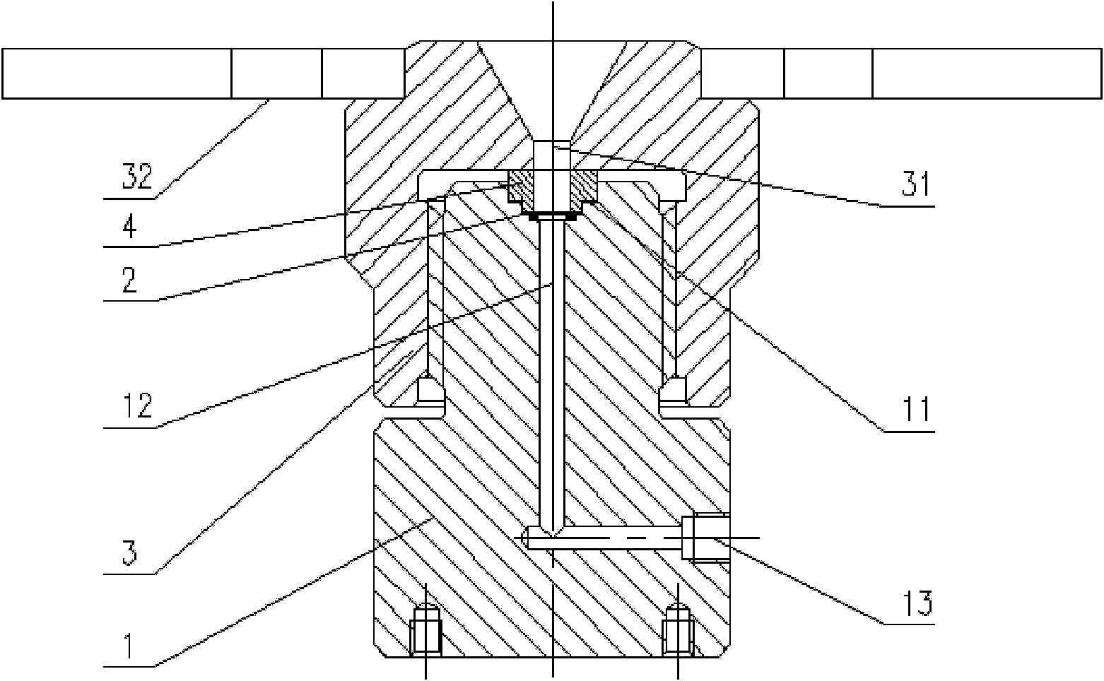
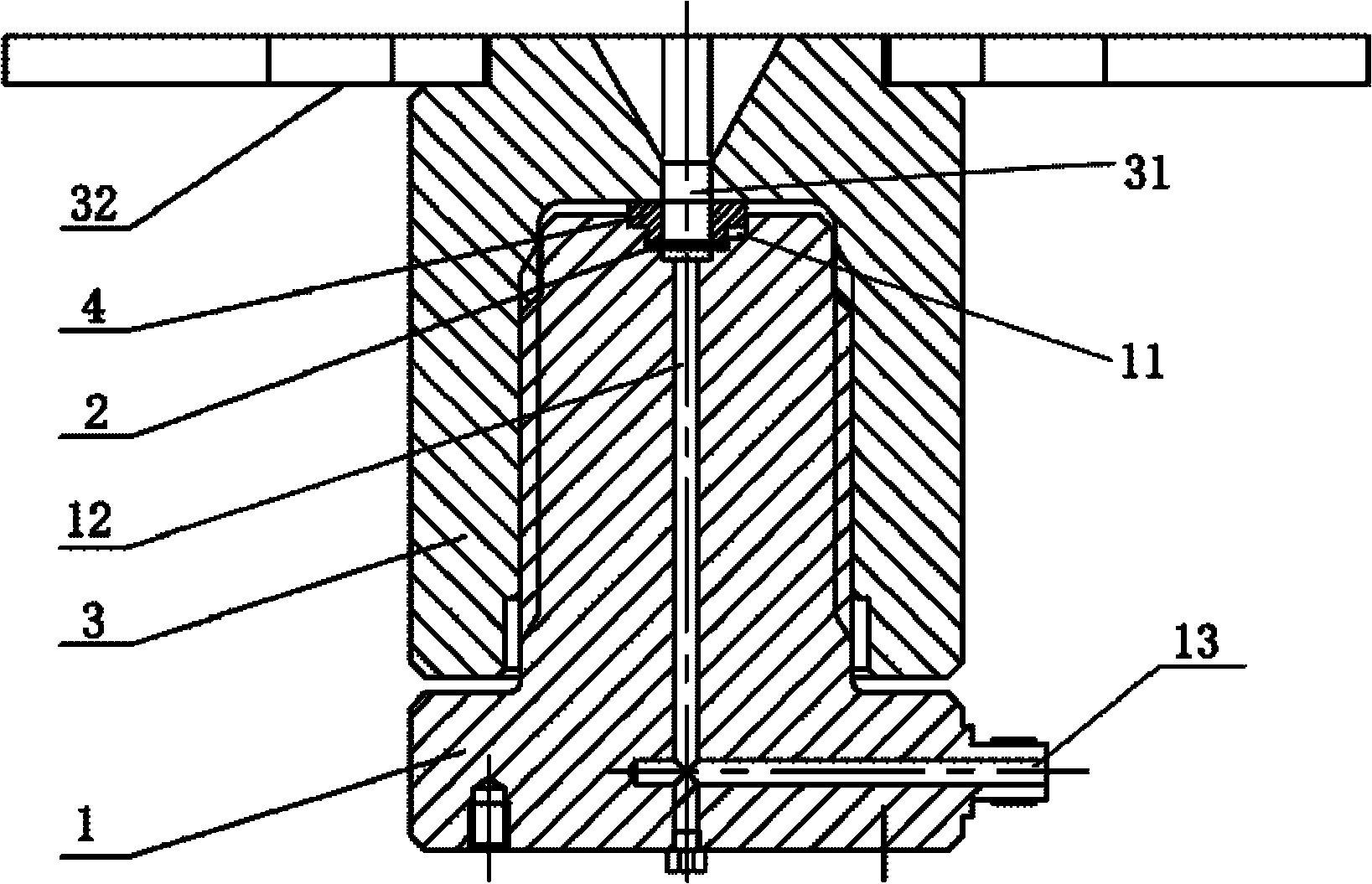
[0035] A. Provide a base 1. The upper end of the base 1 is provided with a sample holding groove 11. The base 1 has a liquid chamber 12. One end of the liquid chamber 12 is connected to the bottom of the sample holding groove 11, and the other end is a liquid inlet. End 13, the liquid inlet end 13 is located at the bottom of the base 1.

[0036] B. Fill the liquid chamber 12 with liquid to discharge the air in the liquid chamber 12; specifically, input liquid from the liquid inlet 13, such as hydraulic oil, when the liquid chamber 12 is filled with liquid, the air in the liquid chamber 12 can be released All out.

[0037] C. Place the sample 2 in the sample holding groove 11, and place an O-ring between the sample 2 and the base 1; the sample 2 matches the sample holding groove 11.

[0038] D. Set and fasten the clamping part 3 on the upper part of t...

Embodiment approach 2

[0049] see figure 1 , 2 As shown, the embodiment of the present invention proposes a sample loading and clamping device, which includes a base 1 and a clamping member 3 . The upper end of the base 1 is provided with a sample accommodating groove 11, and the base 1 has a liquid chamber 12, one end of the liquid chamber 12 is connected to the bottom of the sample accommodating groove 11, and the other end is a liquid inlet 13, and the liquid inlet 13 is located at the lower part of the base; the clip 3 is sleeved on the upper part of the base 1 .

[0050] As an embodiment of the present invention, the clamping member 3 includes a gland 4 , the lower edge of the gland 4 protrudes outward, and the gland 4 is disposed in the sample accommodating groove 11 .

[0051] The clamping part 3 can be a clamping nut, the upper part of the base 1 has an external thread, and the clamping nut is screwed on the base 1 . In addition, the upper end of the clamping nut can also be provided with...


PUM


Abstract

The invention discloses a sample hydraulic burst test method and loading and clamping device. The method comprises the steps of: providing a base, wherein the upper end of the base is provided with a sample accommodating groove, a liquid cavity is arranged in the base, one end of the liquid cavity is communicated with the bottom of the sample accommodating groove, and the other end of the liquid cavity is a liquid inlet end which is positioned at the lower part of the base; filling liquid in the liquid cavity to evacuate air in the liquid cavity; placing a sample in the sample accommodating groove; sheathing and securing a clamping part at the upper part of the base, and remaining the edge of the sample under a clamped condition, wherein the clamping part is provided with a measuring hole communicated with the sample accommodating groove; filling high-pressure liquid from the liquid inlet end to ensure that the sample can be dilated and deformed under the action of the high-pressure liquid till burst, and measuring test data from the measuring holes; and analyzing the test data to obtain material properties.

Description

technical field [0001] The invention relates to a method and a device for testing the performance of metal materials, in particular to a method for testing a sample hydraulic burst and its loading and clamping device. Background technique [0002] Since nuclear facilities, power plants, petrochemical and other equipment are highly dangerous facilities, some structural designs of these facilities are designed according to relatively conservative principles. At the end of the 1970s, the operating time of nuclear power plants in some countries was about to reach the design life, and people were faced with the choice of stopping or continuing to operate. Therefore, it is necessary to test the mechanical properties of materials of in-service equipment structures. Since these materials have been operating under high temperature or radiation conditions for a long time, after a period of service, it is necessary to determine whether the properties of the materials have changed, so ...

Claims


Application Information

Patent Timeline
Patent Type & Authority Applications(China)
IPC IPC(8): G01N3/12
Inventor 寿比南李晓航徐彤
Owner CHINA SPECIAL EQUIP INSPECTION & RES INST
Why Eureka
Try Eureka