Motor vehicle collision energy dissipator and motor vehicle collision device provided with energy dissipator

A technology of energy consumers and motor vehicles, which is applied in the direction of bumpers, etc., can solve the problems of improving the collision ability of motor vehicles, the volume of energy consumers is large, and the pressure level is reduced, so as to reduce the deformation of the car body, quickly absorb energy, and improve Effects of Acceleration and Collision Force

Inactive Publication Date: 2013-01-23
凌建军
View PDF1 Cites 0 Cited by
  • Summary
  • Abstract
  • Description
  • Claims
  • Application Information

AI Technical Summary

Problems solved by technology

[0003] The patent 201010549637.8 submitted by the applicant discloses a motor vehicle collision device with a switch-controlled energy consumer. This patent has the following problems: ① Since the pressure relief valve cylinder (1617, 1631) is opened on the energy consumer base, The volume of the energy dissipator is large; ② When the pressure relief holes (1615, 1629) and the high-pressure communication holes (1613, 1627) are processed, the process holes must be drilled, and then the process holes must be sealed with screws or welded; ③ When drilling When drilling to the bottom of the upper valve cylinder (1607, 1621), the drill bit is easily damaged due to asymmetry; ④The hydraulic pressure at the lower end of the valve stem is not only related to the pressure of the high-pressure buffer chamber and the pressure of the low-pressure buffer chamber, but also related to the pressure of the valve stem. diameter, the contact angle between the valve stem and the injection hole of the base, the chamfer depth of the upper part of the injection hole of the base, and the injection speed of the injection hole; because the pressure increase of the low-pressure buffer chamber will cause the pressure level to be maintained in the later stage to drop, it will not It is beneficial to improve the collision ability of the motor vehicle; ⑤ when the motor vehicle collides, there are two places to discharge liquid: on the one hand, the fluid sprayed from the base injection holes (1603, 1604) is discharged from the discharge pipe (1634) to the antifreeze In the liquid box (22), on the other hand, the antifreeze discharged through the screw joints (17, 18) and the high-pressure connecting pipes (19, 20) is discharged into the air through the adjustment screw inner holes (1611, 1625) (see Figure 12 ); ⑥In the late stage of the collision, because the valve stem will be gradually closed, more antifreeze fluid will enter the annular space between the piston cylinder and the piston ejector rod, and the pressure in the annular space between the piston cylinder and the piston ejector rod will change from negative pressure to Rapidly increase to a very large pressure, the pressure relief valve with holes (1616, 1630) will close the pressure relief hole (patent 201010549637.8 Figure 13 ), once the pressure in the annular space is greater than a certain value, the valve stem will be forcibly pulled up, the effective injection hole area will suddenly increase, and the pressure in the pressure guide tube will drop rapidly, resulting in a decrease in the acceleration of the B-pillar in the later stage of the collision, which cannot achieve the ideal The collision curve; ⑦The size of the drain pipe directly affects the height of the energy consumer

Method used


Image

  • Motor vehicle collision energy dissipator and motor vehicle collision device provided with energy dissipator
  • Motor vehicle collision energy dissipator and motor vehicle collision device provided with energy dissipator
  • Motor vehicle collision energy dissipator and motor vehicle collision device provided with energy dissipator

Examples


no. 1 approach

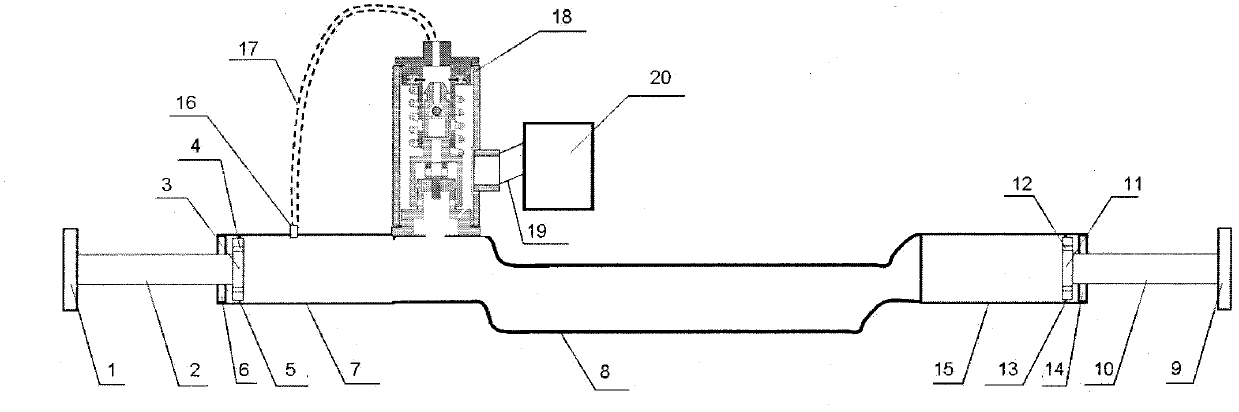
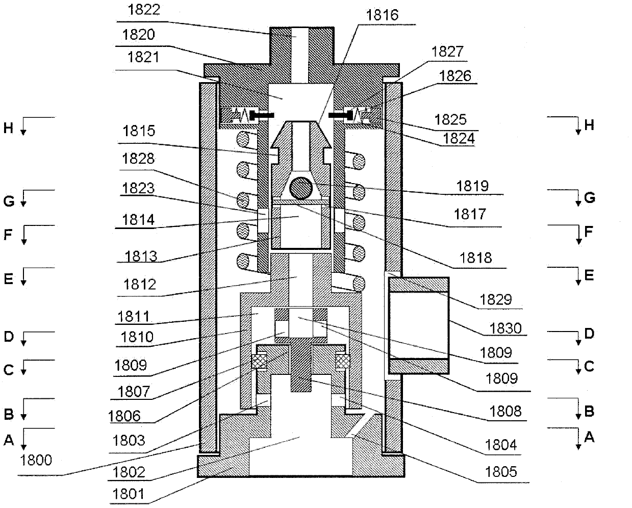
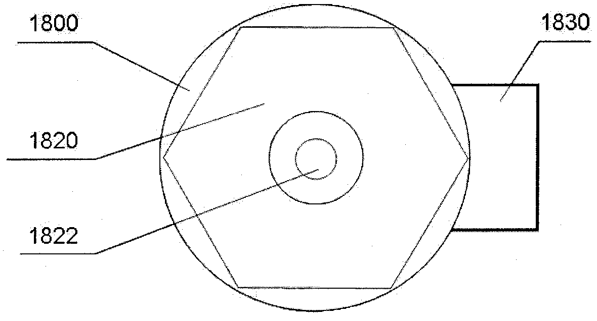
[0053] figure 1 It is a schematic cross-sectional view of a motor vehicle collision device with a motor vehicle collision energy consumer of the present invention; figure 2 It is a schematic cross-sectional view of the motor vehicle collision energy consumer of the present invention; image 3 It is a top view schematic diagram of the motor vehicle collision energy consumer of the present invention; Figure 4 It is a schematic sectional view of the A-A plane of the motor vehicle collision energy consumer of the present invention; Figure 5 It is a schematic sectional view of the B-B plane of the motor vehicle collision energy consumer of the present invention; Figure 6 It is a schematic sectional view of the C-C plane of the motor vehicle collision energy consumer of the present invention; Figure 7 It is a schematic diagram of the D-D plane sectional view of the motor vehicle collision energy consumer of the present invention; Figure 8 It is a schematic sectional view ...

no. 2 approach

[0072] Figure 19 It is a schematic cross-sectional view of the second embodiment of the motor vehicle collision energy consumer; the second embodiment is basically the same as the first embodiment, the only difference is that the upper section of the T-shaped valve stem has changed, that is, the original T-shaped valve stem has been removed. The valve stem communicates with a hole 1809, and a T-shaped valve stem communicates with a groove 1831 on the top surface of the T-shaped valve stem.

Embodiment approach

[0074] The at least one pipe wall injection hole described in the present invention should be understood as greater than or equal to 1, less than or equal to n, and the value range of n is determined by the size of the product and the technical knowledge in the art, which can be 1 or 200. It can also be any number from 1 to 200, so that many different implementations can be formed; the motor vehicle collision energy consumer can be installed on the pressure guide tube or on the piston cylinder, thereby forming different implementations; it should be understood The present invention is not limited to the above-mentioned embodiments, the above-mentioned preferred embodiments are only exemplary, and those skilled in the art can make various equivalent modifications and replacements and different combinations according to the spirit of the present invention to obtain different implementation.


PUM


Abstract

The invention relates to a motor vehicle collision energy dissipator comprising an energy dissipator outer tube, a switch jet hole assembly, a sliding sleeve switch assembly, an adjusting screw assembly, a reversing valve assembly, a T-shaped valve rod, a sliding sleeve switch spring and a liquid discharging pipe, wherein the upper end of the sliding sleeve switch assembly is inserted in a reversing valve cylinder on the adjusting screw assembly and the lower end of the sliding sleeve switch assembly is sleeved at the upper part of the switch jet hole assembly; the lower end of the T-shaped valve rod is inserted in a T-shaped valve rod valve cylinder on the switch jet hole assembly; and the sliding sleeve switch assembly is capable of sliding upwards or downwards according to the change of a downward force applied by the sliding sleeve switch spring, an upward hydraulic pressure applied on a sliding sleeve switch valve cylinder and an upward hydraulic pressure applied to the lower end of the T-shaped valve rod so as to open or partially open or close a switch jet hole on the switch jet hole assembly. Thus, the collision force and the acceleration at the later stage of the motor vehicle collision can be increased and the peak value of the acceleration can also be reduced.

Description

technical field [0001] The invention relates to a motor vehicle collision energy consumer, and also relates to a motor vehicle collision device with the motor vehicle collision energy consumer. Background technique [0002] Since the advent of motor vehicles in 1886, while bringing convenience to human life and work, road traffic accidents have also caused a large number of casualties and property losses. So far, more than 34 million people have died in car accidents worldwide, while hundreds of millions of people have been injured or disabled. According to the "Global Status of Road Safety" report published by the World Health Organization (WHO) on June 15, 2009, the number of deaths involving road traffic accidents in 2008 was as high as 1.2 million, and 20 to 30 million were injured or disabled. The annual economic loss caused by traffic accidents exceeds 700 billion US dollars. [0003] The patent 201010549637.8 submitted by the applicant discloses a motor vehicle coll...

Claims


Application Information

Patent Timeline
Patent Type & Authority Applications(China)
IPC IPC(8): B60R19/32
Inventor 凌建军黄鹂杨铸李越
Owner 凌建军
Why Eureka
Try Eureka