High-precision slotless permanent magnet motor

A permanent magnet motor and permanent magnet linear motor technology, which is applied to synchronous motors with stationary armatures and rotating magnets, electrical components, electromechanical devices, etc., can solve large thrust fluctuations, low motor efficiency and thrust density, vibration and High noise and other problems, achieve the effect of reducing thrust fluctuation and cost, and reducing secondary weight

Inactive Publication Date: 2013-03-27
HARBIN INST OF TECH
View PDF0 Cites 0 Cited by
  • Summary
  • Abstract
  • Description
  • Claims
  • Application Information

AI Technical Summary

Problems solved by technology

[0004] In order to solve the defects of low motor efficiency and thrust density, large thrust fluctuation, high vibration and noise, as well as the secondary weight and high cost of the motor, the present invention proposes a high-precision slotless permanent magnet motor

Method used


Image

  • High-precision slotless permanent magnet motor
  • High-precision slotless permanent magnet motor
  • High-precision slotless permanent magnet motor

Examples


specific Embodiment approach 1

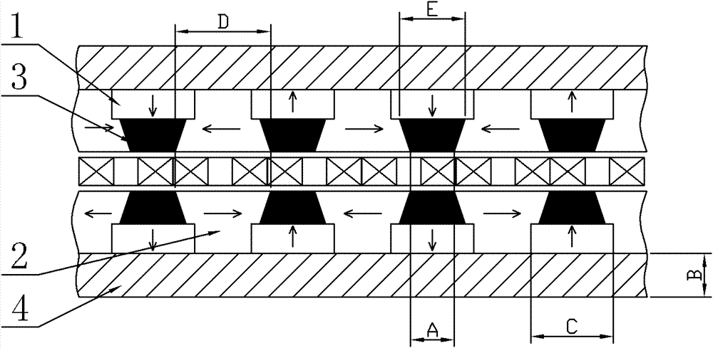
[0011] Specific implementation mode one: combine figure 1 Describe this embodiment, the high-precision slotless permanent magnet motor of this embodiment is a flat permanent magnet linear motor, which includes a primary and a secondary; The primary is located inside the bilateral secondary, and there is an air gap between the primary and bilateral secondary; the secondary is composed of a main permanent magnet 1, an auxiliary permanent magnet 2, a concentrating magnet 3 and a yoke plate 4, and the main permanent magnet 1 is a flat permanent magnet , the flat plate-shaped permanent magnet is magnetized in parallel, and the auxiliary permanent magnet 2 is a T-shaped permanent magnet whose cross section is a trapezoid and a rectangle or a rectangle and a rectangle. The T-shaped permanent magnet is magnetized in parallel, and the magnet 3 It is a trapezoidal or rectangular magnet gathering body with a cross section. Along the direction of motion, the main permanent magnet 1 and t...

specific Embodiment approach 2

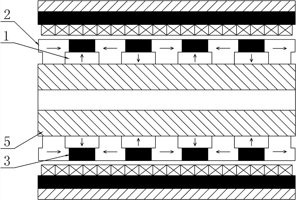
[0012] Specific implementation mode two: combination figure 2 and image 3Describe this embodiment, the high-precision slotless permanent magnet motor of this embodiment is a cylindrical permanent magnet linear motor, which includes a primary and a secondary; the primary adopts a coreless structure or a structure with an iron core and no slots, and the primary is located outside the secondary , there is an air gap between the primary and the secondary; the secondary is composed of a main permanent magnet 1, an auxiliary permanent magnet 2, a magnet concentrator 3 and a magnetic yoke tube 5, and the main permanent magnet 1 is an annular permanent magnet with a rectangular axial cross section , the annular permanent magnet is radially magnetized or radially parallel magnetized, and the auxiliary permanent magnet 2 is an annular T-shaped permanent magnet whose axial cross section is a trapezoid and a rectangle or a rectangle and a rectangle. The T-shaped permanent magnet is mag...

specific Embodiment approach 3

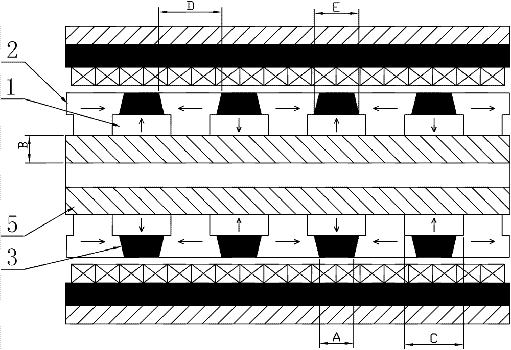
[0013] Specific implementation mode three: combination Figure 4 to Figure 13 Describe this embodiment. The high-precision slotless permanent magnet motor in this embodiment is a planar permanent magnet motor, which includes a primary and a secondary; On one side of the secondary, there is an air gap between the primary and the secondary; the secondary is composed of a main permanent magnet 1, an auxiliary permanent magnet 2, a concentrating magnet 3 and a yoke plate 4, and the main permanent magnet 1 is a flat permanent magnet 11, so The flat-shaped permanent magnet 11 described above is magnetized parallel to the Z direction, and the auxiliary permanent magnet 2 is a composite permanent magnet whose cross section is a trapezoid and a rectangle or a rectangle and a rectangle. The composite permanent magnet is parallel to the X or Y directions. Magnetization: The magnet gathering body 3 is a trapezoidal or rectangular cross section in the X direction and the Y direction, and a...


PUM


Abstract

The invention provides a high-precision slotless permanent magnet motor, relating to the motor field. The motor is used for solving the defects that efficiency and thrust density are low, thrust fluctuation is strong as well as vibration and noise are high, and the problem that secondary weight and motor cost are high. The motor is characterized in that a secondary electromagnetic structure is optimized, thus the secondary weight is decreased, the thrust fluctuation and the cost of the motor are reduced, and air-gap magnetic density, the sine degree of an air-gap field, the electromagnetic thrust of the motor as well as the efficiency and control precision of the motor are improved. The secondary structure comprises master permanent magnets, auxiliary permanent magnets, a magnetic-collecting body and a yoke plate, and the widths of specific side faces among the master permanent magnets, the auxiliary permanent magnets, the magnetic-collecting body and the yoke plate are limited; each master permanent magnet is provided with a rectangle cross section; each auxiliary permanent magnet is provided with a mixed ladder-shaped and rectangle cross section or a mixed rectangle and rectangle cross section; the magnetic-collecting body is provided with a ladder-shaped or rectangle cross section; the master permanent magnets and the auxiliary permanent magnets are successively fixed on the magnetic-conducting yoke plate in a radial arrangement mode; the master permanent magnets, the auxiliary permanent magnets and the magnetic-collecting body are closely coordinated; every two adjacent master permanent magnets are opposite in magnetizing directions; and every two adjacent auxiliary permanent magnets are opposite in magnetizing directions.

Description

technical field [0001] The invention relates to the field of motors, in particular to a high-precision slotless permanent magnet motor. Background technique [0002] Figure 16 Shown is a schematic structural diagram of a traditional double-sided coreless linear permanent magnet synchronous motor. The secondary of the motor is composed of a yoke plate and a flat permanent magnet. The permanent magnets are magnetized parallel to the direction perpendicular to the direction of motion. The permanent magnets are magnetized in the same direction, with the primary located between the two secondary plates. The normal component of the magnetic force line generated by the permanent magnet passes through the primary vertically, and the energized primary winding interacts with the magnetic field of the secondary permanent magnet to generate electromagnetic force and push the mover to move in a straight line. [0003] However, the linear motor has the following disadvantages: the air-...

Claims


Application Information

Patent Timeline
Patent Type & Authority Patents(China)
IPC IPC(8): H02K41/02H02K41/00H02K21/12
Inventor 寇宝泉赵斌超曹海川
Owner HARBIN INST OF TECH
Why Eureka
Try Eureka