Ring winding magnetic field modulation linear motor

A technology of toroidal winding and magnetic field modulation, applied in magnetic circuits, electrical components, electromechanical devices, etc., can solve the problems of material waste, complex insulation process, and low efficiency

Inactive Publication Date: 2017-07-21
HARBIN INST OF TECH
View PDF5 Cites 5 Cited by
  • Summary
  • Abstract
  • Description
  • Claims
  • Application Information

AI Technical Summary

Problems solved by technology

[0003] The present invention aims to solve the problems of the end length of the winding of the traditional linear permanent magnet motor and the waste of materials caused by the winding mode of the winding, the complicated insulation p...

Method used


Image

  • Ring winding magnetic field modulation linear motor
  • Ring winding magnetic field modulation linear motor
  • Ring winding magnetic field modulation linear motor

Examples


specific Embodiment approach 1

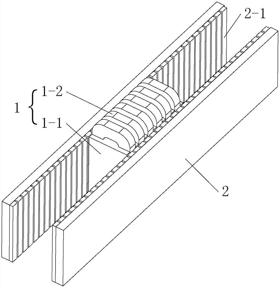
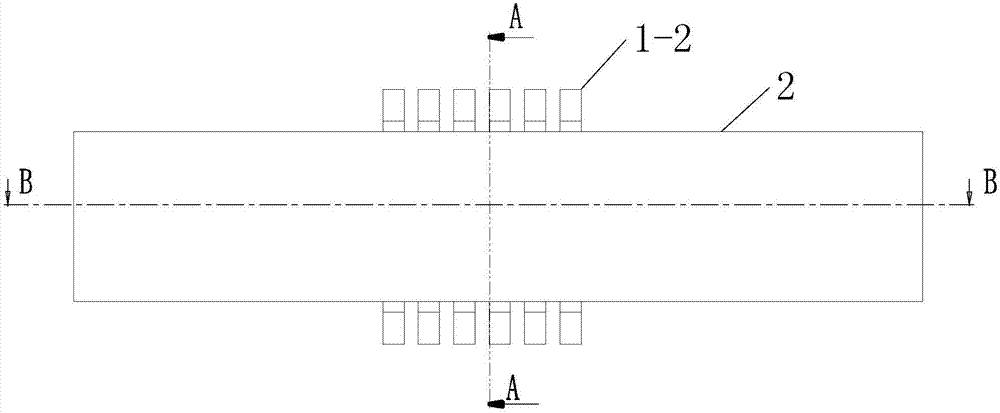
[0111] Specific implementation mode one: see Figure 2 to Figure 5 Describe this embodiment, the ring winding magnetic field modulation linear motor described in this embodiment, it includes primary 1 and secondary 2, and there is an air gap between them,

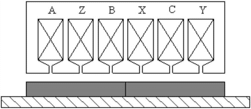
[0112] The secondary 2 is a double-sided structure, and the primary 1 is arranged between the two sides, and a secondary permanent magnet 2-1 is arranged on the air gap side of the bilateral structure, and the magnetization direction of the secondary permanent magnet 2-1 is perpendicular to the direction of motion, and The magnetization directions of the two adjacent secondary permanent magnets 2-1 on one side are opposite, and the magnetization directions of the secondary permanent magnets 2-1 corresponding to the two sides are the same,

[0113] The primary 1 includes a primary iron core 1-1 and a primary winding 1-2. Primary slots are longitudinally opened on the left and right air gap sides of the primary iron core 1-1,...

specific Embodiment approach 2

[0121] Specific implementation mode two: see Figure 6 to Figure 8 Describe this embodiment, the circular winding magnetic field modulation linear motor described in this embodiment includes a primary 1 and a secondary 2, and there is an air gap between them;

[0122] The secondary 2 is a "concave" three-sided structure, and the primary 1 is set in the groove of the "concave" three-sided structure, and the air gap side of the "concave" three-sided structure is provided with a secondary permanent magnet 2-1 , the magnetization direction of the secondary permanent magnet 2-1 is perpendicular to the direction of motion, and the magnetization direction of the two adjacent secondary permanent magnets 2-1 on one side is opposite, and the secondary permanent magnet 2 at the corresponding position on the three sides The magnetization direction of -1 is the same;

[0123]The primary 1 includes a primary iron core 1-1 and a primary winding 1-2. Primary slots are longitudinally opened o...

specific Embodiment approach 3

[0133] Specific implementation mode three: see Figure 9 to Figure 11 Describe this embodiment, the circular winding magnetic field modulation linear motor described in this embodiment includes a primary 1 and a secondary 2, and there is an air gap between them;

[0134] The primary 1 includes a main primary core 1-1, a primary winding 1-2 and two auxiliary primary cores 1-3; the two auxiliary primary cores 1-3 are located on both sides of the main primary core 1-1, and on the main primary core 1- The left and right air gap sides of 1 have primary slots along the longitudinal direction, and primary windings 1-2 are arranged in the slots, and the primary windings 1-2 are realized by ring windings, and are in the form of three-phase symmetrical windings;

[0135] The secondary 2 is a double-sided structure, and the two sides are respectively located between the main primary core 1-1 and the two auxiliary primary cores 1-3, and a secondary permanent magnet 2-1 is embedded on each...


PUM


Abstract

The invention discloses a ring winding magnetic field modulation linear motor, which belongs to the field of motors and solves the problems of material waste, complicated insulation process between windings, large motor thrust fluctuation and low frequency caused by the long end part of the traditional linear permanent magnet motor winding and the winding mode of the winding. The ring winding magnetic field modulation linear motor comprises a primary winding and a secondary winding, a gap exists between the primary winding and the secondary winding, by adopting pole-slot match between the primary winding and the secondary winding and the ring winding, non-uniform air gap permeance plays a role of pole changing, the magnetic motive force of the primary winding and the air gap permeance interact mutually, a magnetic field with the same pole number as secondary permanent magnets is generated, the two magnetic fields interact mutually to generate a constant thrust, and thus, the limitation that the pole number of the primary winding and the pole number of the secondary winding of the traditional linear permanent magnet synchronous motor need to be the same is further broken. The pole-pairs number P of the secondary permanent magnets, the slot number Q per side of the primary winding and the pole-pairs number S of the primary winding fundamental magnetic motive force meet the following relationship: P=Q+/-S. The ring winding magnetic field modulation linear motor can be applied to low speed, great acceleration, high output thrust and other situations.

Description

technical field [0001] The invention belongs to the field of motors. Background technique [0002] The armature core tooth pitch τ of the traditional single-sided flat three-phase linear permanent magnet synchronous motor t The pole distance τ from the permanent magnet p Satisfy the relation 3τ t =τ p , a coil side is embedded in each slot, and the coil pitch is equal to the pole pitch. This winding structure is called an integer slot single-layer winding. The winding of the motor is as figure 1 As shown, the coil of the A-phase winding is wound in the first slot and the fourth slot, while crossing the second and third slots, and the coil of the C-phase winding is wound in the second and fifth slots. Wraps inside the slot, while crossing the third and fourth slots, and so on. The main problem of this type of winding is that the ends of the winding coils of each phase exposed outside the core teeth are relatively long, and the winding coils of each phase cross each othe...

Claims


Application Information

Patent Timeline
IPC IPC(8): H02K41/03
CPCH02K41/031H02K2201/03H02K2213/03
Inventor 寇宝泉邵一张赫
Owner HARBIN INST OF TECH
Why Eureka
Try Eureka