High thrust density cylinder type linear electric motor
A linear motor, high thrust technology, applied in synchronous machines, electrical components, electromechanical devices, etc., can solve the problems of large positioning force, complex manufacturing process, low overload capacity and thrust density of linear motors, and can eliminate the positioning force and improve the Overload capacity and thrust density, the effect of simplifying the manufacturing process
- Summary
- Abstract
- Description
- Claims
- Application Information
AI Technical Summary
Problems solved by technology
Method used
Image
Examples
specific Embodiment approach 1
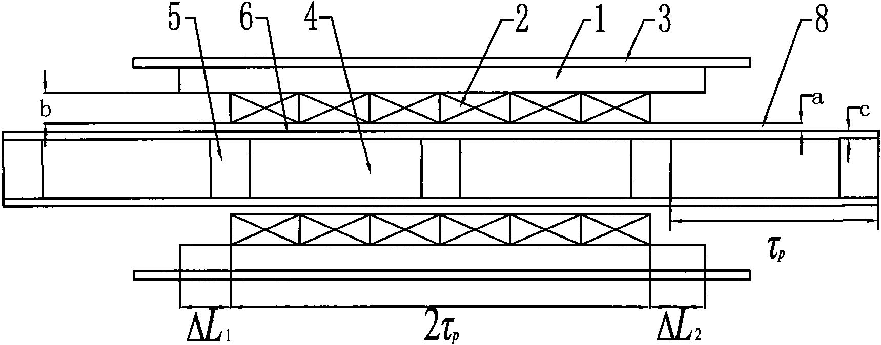
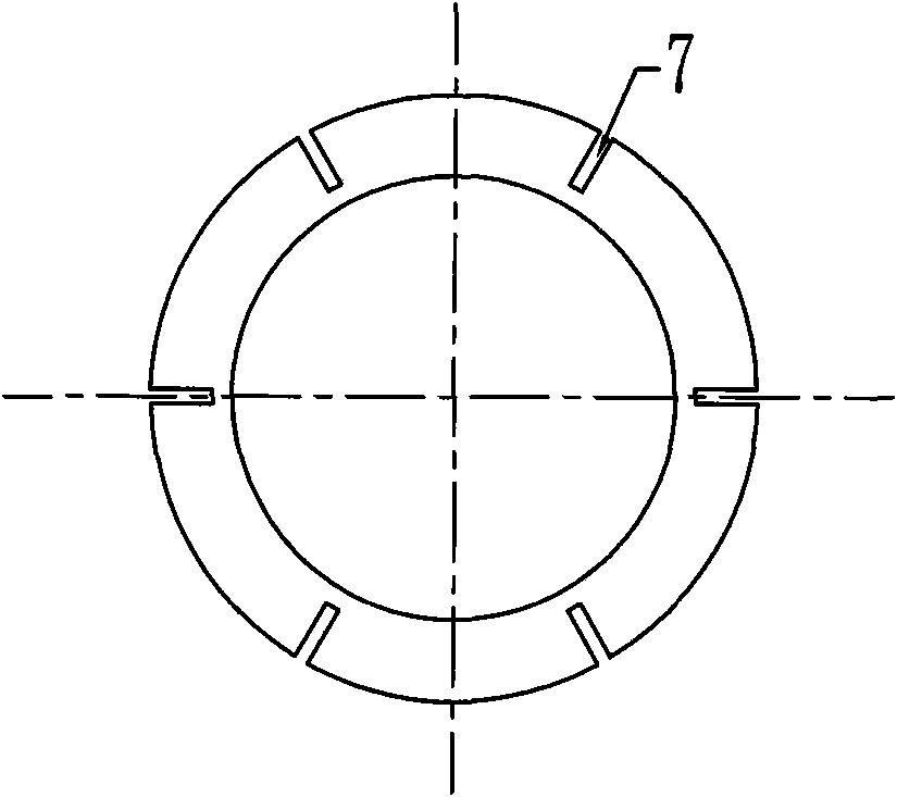
[0012] Specific implementation mode one: combine figure 1 with image 3 Describe this embodiment, the motor of this embodiment is an outer armature structure, the primary is composed of an armature core 1, an armature winding 2 and a casing 3; Both the magnet 4 and the magnetic yoke 5 are cylindrical; the permanent magnet 4 and the magnetic yoke 5 are arranged at intervals in the cylindrical fixing part 6; the armature core 1 is cylindrical, and the armature core 1 The outer wall of the armature core 1 is uniformly opened with radial grooves 7 opening outwards in the radial direction. The width of the grooves 7 is 0.1 mm to 2 mm. The outer wall of the armature core 1 is fixed on the inner wall of the cylindrical casing 3; The coils of the armature winding 2 are circular coils, and the coils forming the armature winding 2 of each phase are arranged sequentially on the inner wall of the armature core 1; an air gap 8 is arranged between the inner wall of the coil and the outer ...
specific Embodiment approach 2
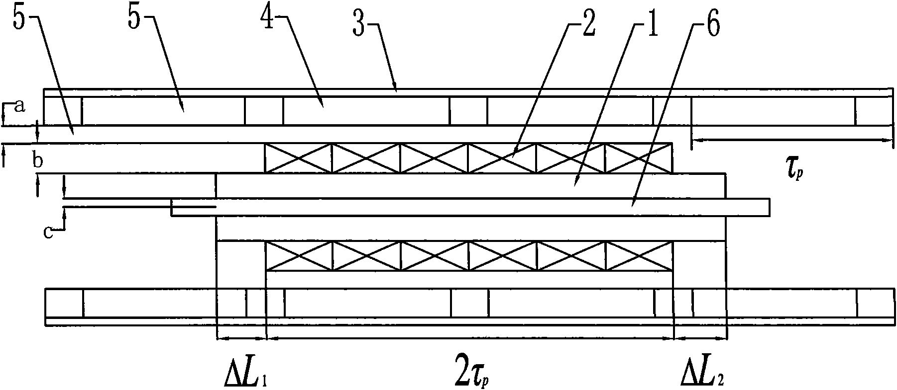
[0015] Specific implementation mode two: combination figure 2 with image 3 To illustrate this embodiment, the motor of this embodiment is an inner armature structure; the primary is composed of an armature core 1, an armature winding 2 and a fixing member 6; the secondary is composed of a permanent magnet 4, a magnetic yoke 5 and a casing 3; The permanent magnet 4 and the magnetic yoke 5 are circular; the permanent magnet 4 and the magnetic yoke 5 are arranged at intervals in the cylindrical casing 3; the armature core 1 is cylindrical, and the armature The outer wall of the iron core 1 is evenly opened with radial grooves 7 opening outwards in the radial direction. The width of the grooves 7 is 0.1 mm to 2 mm. The inner wall of the armature core 1 is fixed on a cylindrical or cylindrical fixing member 6 on the outer wall of the armature winding 2; the coils of the armature winding 2 are circular coils, and the coils forming the armature winding 2 of each phase are arranged...
specific Embodiment approach 3
[0018] Specific embodiment three: the difference between this embodiment and specific embodiment one or two is that the permanent magnet 4 adopts a rare earth permanent magnet, which is magnetized in the axial direction, and the magnetization direction of the adjacent permanent magnet 4 is opposite; the fixing member 6 adopts a non-magnetic material, Such as stainless steel; the casing 3 is made of light non-magnetic material, such as aluminum alloy; the magnetic yoke 5 is made of magnetic material with high saturation flux density. Other compositions and connection modes are the same as those in Embodiment 1 or 2.
PUM
 Abstract
Description
Claims
Application Information
 - R&D
- Intellectual Property
- Life Sciences
- Materials
- Tech Scout
- Unparalleled Data Quality
- Higher Quality Content
- 60% Fewer Hallucinations
Browse by: Latest US Patents, China's latest patents, Technical Efficacy Thesaurus, Application Domain, Technology Topic, Popular Technical Reports.
© 2025 PatSnap. All rights reserved.Legal|Privacy policy|Modern Slavery Act Transparency Statement|Sitemap|About US| Contact US: help@patsnap.com


