Drive circuit capable of improving power factors of alternating current light emitting diode (AC LED) lamp

A technology for driving circuits and LED light strings, which is applied in the layout of electric light circuits, conversion devices for output power, and high-efficiency power electronic conversion, etc. The effect of improving reliability and high power factor

Active Publication Date: 2011-09-14
NO 771 INST OF NO 9 RES INST CHINA AEROSPACE SCI & TECH
View PDF3 Cites 47 Cited by
  • Summary
  • Abstract
  • Description
  • Claims
  • Application Information

AI Technical Summary

Problems solved by technology

[0005] The passive power factor correction circuit has a simple structure, but it is large in size and heavy in weight, so it is not suitable for use in LED lighting fixtures
The active power factor correction circuit is

Method used


Image

  • Drive circuit capable of improving power factors of alternating current light emitting diode (AC LED) lamp
  • Drive circuit capable of improving power factors of alternating current light emitting diode (AC LED) lamp
  • Drive circuit capable of improving power factors of alternating current light emitting diode (AC LED) lamp

Examples


Embodiment 1

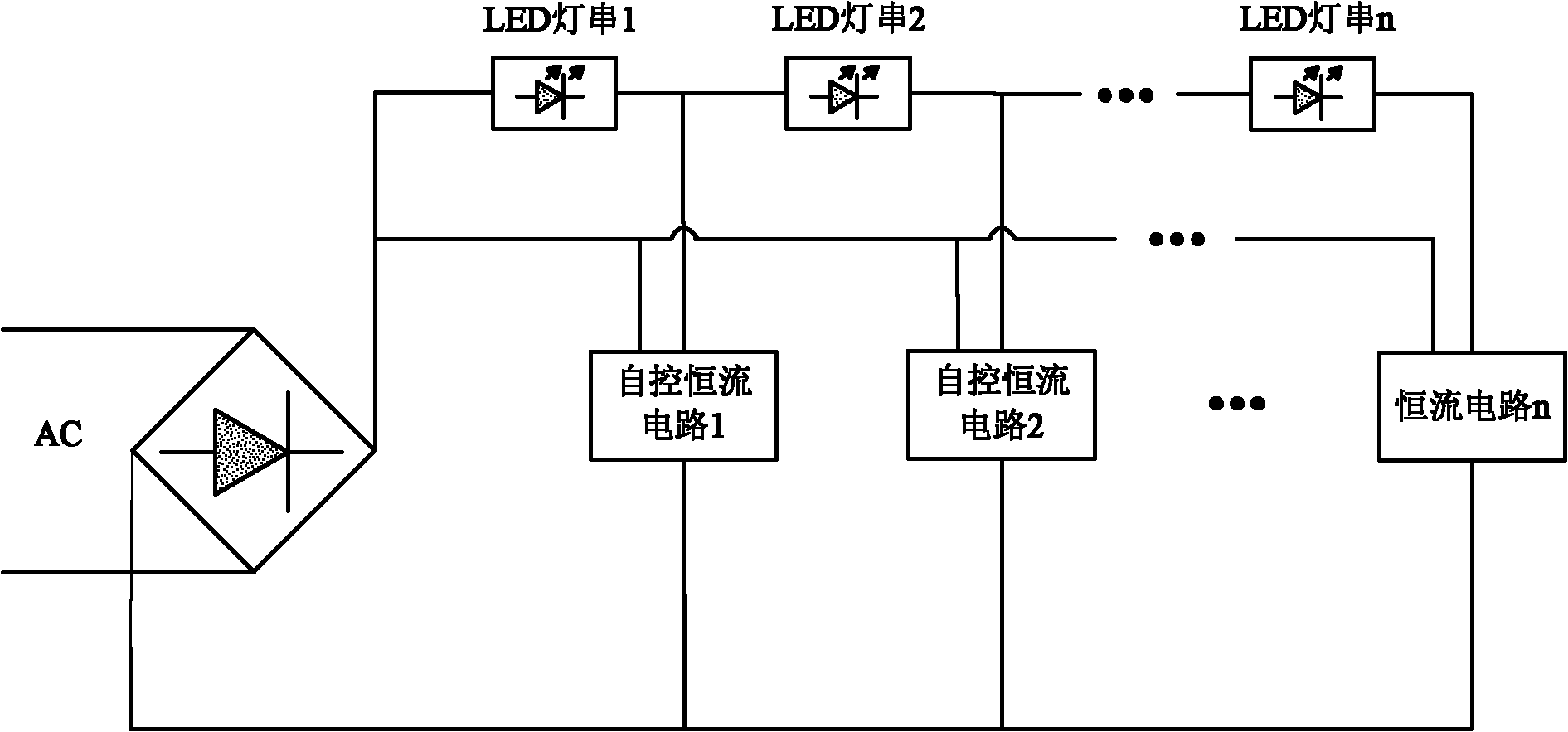
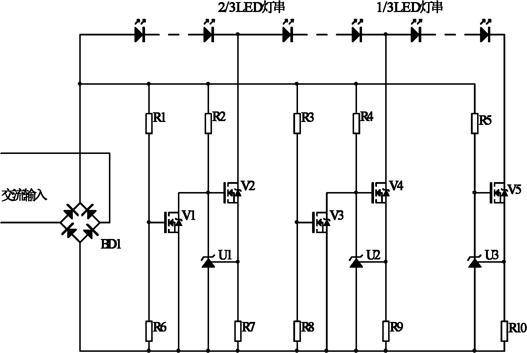
[0023] Such as figure 2 As shown, a drive circuit that can improve the power factor of AC LED lamps is composed of a rectifier bridge BD1, three series-connected LED lamp strings (20 per string) and three corresponding self-controlled constant current circuits.

[0024] The three self-controlled constant current circuits are respectively connected to 1 / 3, 2 / 3 of the series LED light string and the negative end of the light string. The rectifier bridge BD1 rectifies the 220V / 50Hz alternating current into a 100Hz steamed bun wave. Resistors R1, R2, R6, R7, MOS tubes V1, V2 and voltage reference U1 form the first self-control constant current circuit; resistors R3, R4, R8, R9, MOS tubes V3, V4 and voltage reference U2 form the second self-control circuit Constant current circuit, resistors R5, R10, MOS transistor V5 and voltage reference U3 constitute the last constant current circuit.

[0025] When the input voltage is below 1 / 3 of the rated range (<73.3V), V1 is turned off a...

Embodiment 2

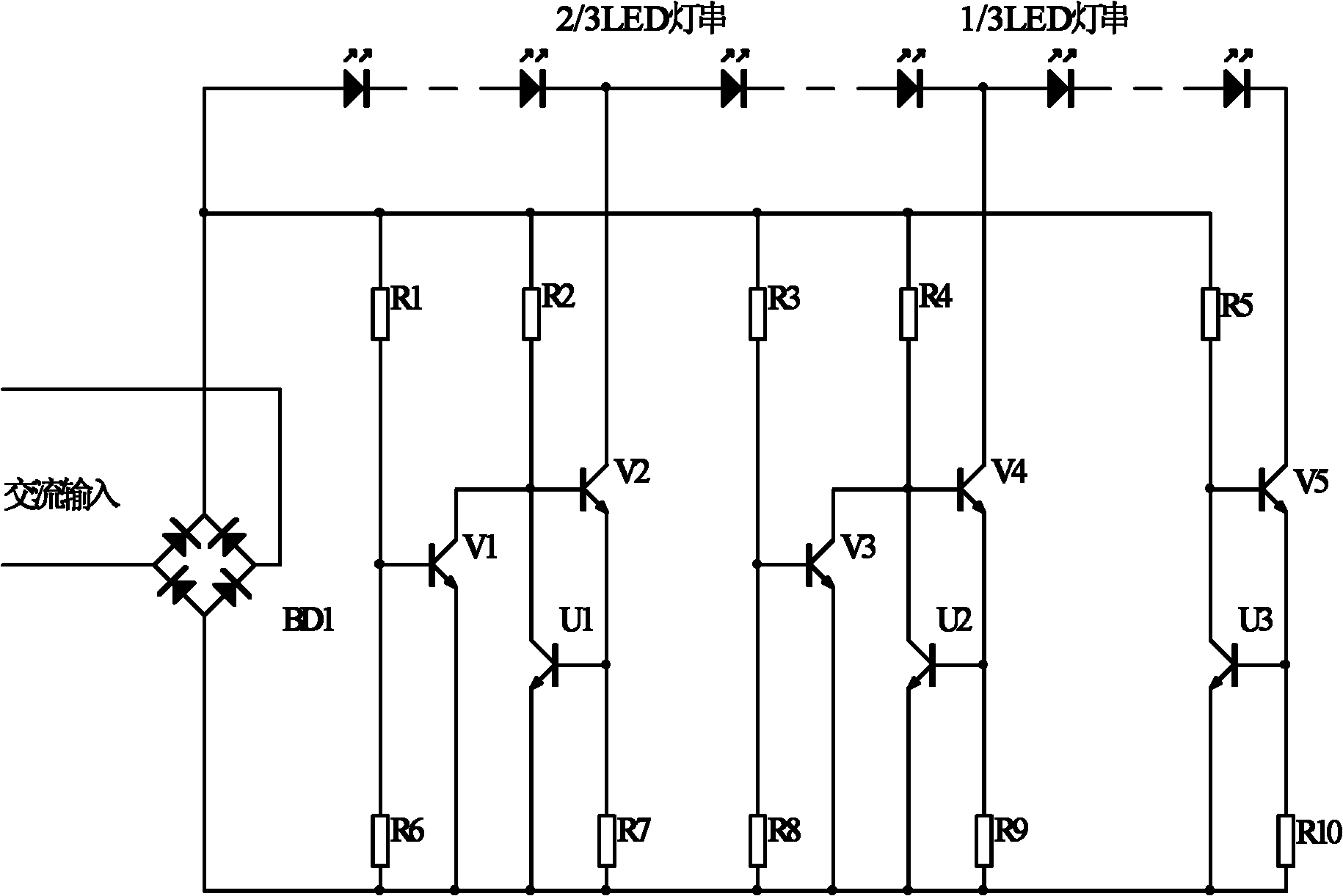
[0036] Such as image 3 As shown, another drive circuit that can improve the power factor of AC LED lamps differs from the first embodiment in that the MOS transistors V1, V2, V3, V4, V5 and voltage references U1, U2, U3 can be replaced by triodes. The working principle of this embodiment is the same as that of Embodiment 1, and will not be repeated here.

[0037] The present invention can correct the waveform of the input current by controlling the conduction quantity of the LED lamp strings and limiting the current flowing through the LED lamp strings in sections, so as to achieve the purpose of power factor correction. Using the power factor correction drive circuit of the present invention, the input voltage and current waveforms are as follows Figure 4 As shown, the power factor is greatly improved to around 0.97-0.99.


PUM


Abstract

The invention discloses a drive circuit capable of improving power factors of an alternating current light emitting diode (AC LED) lamp. The drive circuit comprises a rectifier bridge, wherein two input terminals of the rectifier bridge are connected with AC voltage. The drive circuit is characterized in that: the positive output terminal of the rectifier bridge is connected with positive terminals of n serially connected LED lamp strings and detection terminals of n self-controlled constant-current circuits; the negative output terminal of the rectifier bridge is connected with the output terminals of the n self-controlled constant-current circuits; the negative terminal of the nth LED lamp string is connected with the input terminal of the self-controlled constant-current circuit with serial number of n, wherein n is more than or equal to 2 but less than or equal to 10; and in the n serially connected LED lamp strings, the number of LEDs in each lamp string is the same. The drive circuit uses a circuit design method of automatically controlling operating modes of the n constant-current circuits in stages by detecting AC input voltage so as to greatly improve the power factor, reliability and safety of the AC LED; and an AC/DC converter is not needed to be installed in the lamp, and then the failure rate of equipment is reduced. Furthermore, the drive circuit has the advantages of novel structure, simple circuit, high power factor, long service life, good power-saving effect and the like.

Description

technical field [0001] The invention relates to a driving circuit of an LED illuminating lamp, in particular to a control circuit capable of improving the power factor of an AC LED (light emitting diode directly input by alternating current) illuminating lamp. Background technique [0002] With the increasingly wide application of power electronic devices, the problem of harmonic pollution has attracted more and more attention. Electrical equipment in Europe must now comply with the European norm EN61000-3-2. This requirement applies to most appliances with an input power of 75W or more, and it specifies the maximum amplitude of power frequency harmonics including up to the 39th harmonic. While there is no such requirement in the US, power supply manufacturers looking to sell their products globally are designing products to meet this requirement. [0003] Using power factor correction technology, the AC input current waveform can completely track the AC input voltage wave...

Claims


Application Information

Patent Timeline
IPC IPC(8): H05B37/02H02M1/42
CPCY02B70/126Y02B20/40Y02B70/10
Inventor 段晓飞苏理王琛
Owner NO 771 INST OF NO 9 RES INST CHINA AEROSPACE SCI & TECH
Why Eureka
Try Eureka