
Hair straightener

A hair and main handle technology, applied in hairdressing equipment, curling or perming devices, clothing, etc., can solve the problems of water tank drop, easy loosening, circuit board short circuit, etc., to achieve easy opening and closing, not easy to fall off, installation and The effect of easy disassembly

Active Publication Date: 2012-11-21
ZHEJIANG PAITER ELECTRIC
View PDF0 Cites 0 Cited by
  • Summary
  • Abstract
  • Description
  • Claims
  • Application Information

AI Technical Summary

Problems solved by technology

However, the current water tank is in the shape of a rectangular parallelepiped. When the amount of water in the water tank is very small, it is easy to cause the hair to be burnt without absorbing water and unable to discharge water vapor; at the same time, the bottom of the existing water tank is smooth. Rarely, the water at the spout cannot be absorbed causing the hair to burn
The water tank installed on the existing hair straightener is not firm, and it is easy to loosen. The water tank falling off during use will cause the hair to be burnt, and the water tank will fall and cause damage; at the same time, the installation and disassembly of the water tank are too cumbersome and inconvenient to use
Simultaneously the water tank of existing hair straightening device is all located at the front end of body, promptly is arranged on the top of heating body, when using hair straightening device, because water tank is close to heating body, heating body just directly heats water tank, and the water tank in the water tank The air pressure is easy to rise and cause water to overflow from the water tank, and a short circuit will occur when the overflowed water flows into the circuit board, so there is a safety hazard in the existing hair straightener; It is inconvenient to disassemble the water tank directly during the use of the hair straightener

Method used


Image

  • Hair straightener
  • Hair straightener
  • Hair straightener

Examples


Embodiment Construction

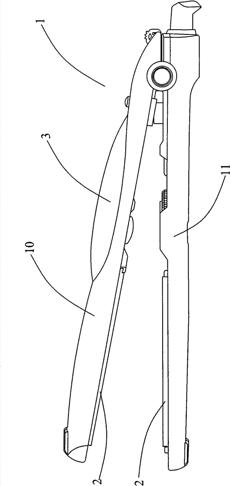
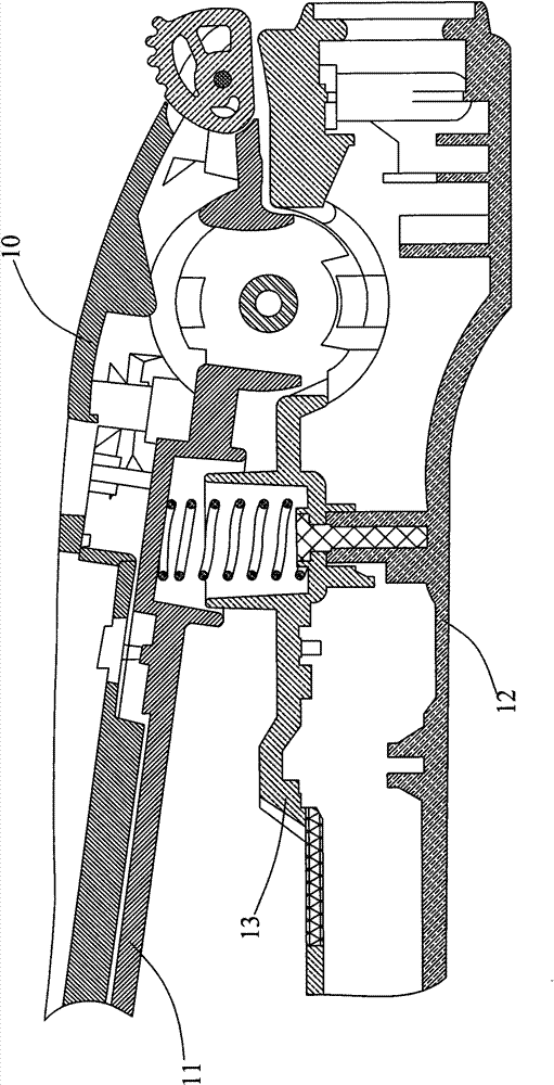
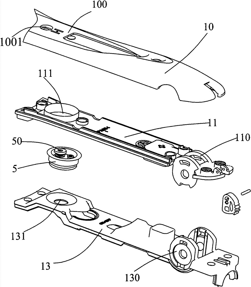
[0030] In order to have a further understanding of the structure and achieved effects of the present invention, the detailed description is as follows in conjunction with the accompanying drawings and preferred embodiments.

[0031] Such as figure 1 and figure 2 As shown, the hair straightener of the present invention includes a handle 1, a clamping part 2, a water tank 3 and a power circuit (not shown in the figure), the handle 1 is divided into an upper main handle 10, a last handle 11, a lower main handle For the handle 12 and the next handle 13, there are two clamping parts 2 in the present invention, and they are arranged oppositely. The two clamping parts 2 are embedded and fixed on the front ends of the upper main handle 10 and the lower main handle 12. 11 is embedded and fixed on the end of the upper main handle 10 away from the clamping part 2, the next handle 13 is embedded and fixed on the end of the lower main handle 12 away from the clamping part 2, and the uppe...


PUM


Abstract

The invention discloses a hair straightener, comprising a handle, clamping parts, a water tank and a power supply circuit, wherein the handle comprises an upper main handle, an upper secondary handle, a lower main handle and a lower secondary handle; the clamping parts are two in number, are arranged oppositely and are fixedly embedded at the front ends of the upper main handle and the lower main handle; the upper secondary handle is embedded and fixed at one end of the upper main handle far away from the clamping parts; the lower secondary handle is fixedly embedded at one end of the lower main handle far away from the clamping parts; the upper secondary handle is pivoted with the lower secondary handle; the water tank is arranged on the upper main handle; a button device which can control the size of air pressure and the size of the generated steam in the water tank is arranged between the lower main handle and the lower secondary handle; and the power supply circuit is arranged at the bottom in the lower main handle and is electrically connected with heating bodies in the clamping parts. By means of the hair straightener disclosed by the invention, water in the water tank can be effectively utilized, and the condition that the hair is burnt can be avoided even when water is less.

Description

technical field [0001] The invention relates to a hair straightener, in particular to a hair straightener capable of adjusting the size of steam and having a water tank that is easy to assemble and disassemble. Background technique [0002] At present, hair straighteners are more and more widely used, especially by young people. Hair straighteners can straighten curly hair and shape better hairstyles. The button used to control the water vapor of the existing hair straightener is located on the side of the hair straightener and protrudes from the surface of the body. Therefore, during use, the button is easy to be accidentally touched by hand and the steam will be turned off unintentionally, causing the hair to burn . When straightening the hair, it is necessary to convert the liquid exported from the water tank into steam by heating, so as to avoid the hair from being burnt during the straightening process. However, the current water tank is in the shape of a rectangular...

Claims


Application Information

Patent Timeline
Patent Type & Authority Patents(China)
IPC IPC(8): A45D2/00
Inventor 王仁通
Owner ZHEJIANG PAITER ELECTRIC
Learn More