Upper spray cooling device arranged among finishing mill racks

A cooling device and technology between stands, applied in metal rolling, metal rolling, metal processing equipment and other directions, can solve the problem of uneven cooling distribution, and achieve the effect of reducing temperature drop, reducing production cost and avoiding waste of resources

Inactive Publication Date: 2011-09-21
BAOSHAN IRON & STEEL CO LTD +1
View PDF13 Cites 2 Cited by
  • Summary
  • Abstract
  • Description
  • Claims
  • Application Information

AI Technical Summary

Problems solved by technology

[0011] The object of the present invention is to provide a kind of upper spray cooling device arranged between the finish rolling stand, under the premise of not affecting the cooling stability of the finish rolling strip, the device can realize the According to the cooling process requirements of different widths of the finished strip, the gap cooling water of the finishing stand corresponding to the width of the strip passage is established correspondingly to realize the corresponding change of the cooling water of the finishing stand in the width of the strip, thereby adjusting the cooling water of the finishing stand The cooling width area in the channel width direction is to overcome the phenomenon that the cooling device in the prior art cannot solve the problem of uneven cooling distribution in the width direction of the strip, and to reduce the temperature drop at the edge of the strip in the finishing rolling area, ensuring that the strip The purpose of uniformity of steel plate shape, mechanical properties, temperature and phase transformation in the width direction of the strip

Method used


Image

  • Upper spray cooling device arranged among finishing mill racks
  • Upper spray cooling device arranged among finishing mill racks
  • Upper spray cooling device arranged among finishing mill racks

Examples


Embodiment Construction

[0034] Attached below Figure 1-5 A preferred embodiment of the present invention is specifically introduced.

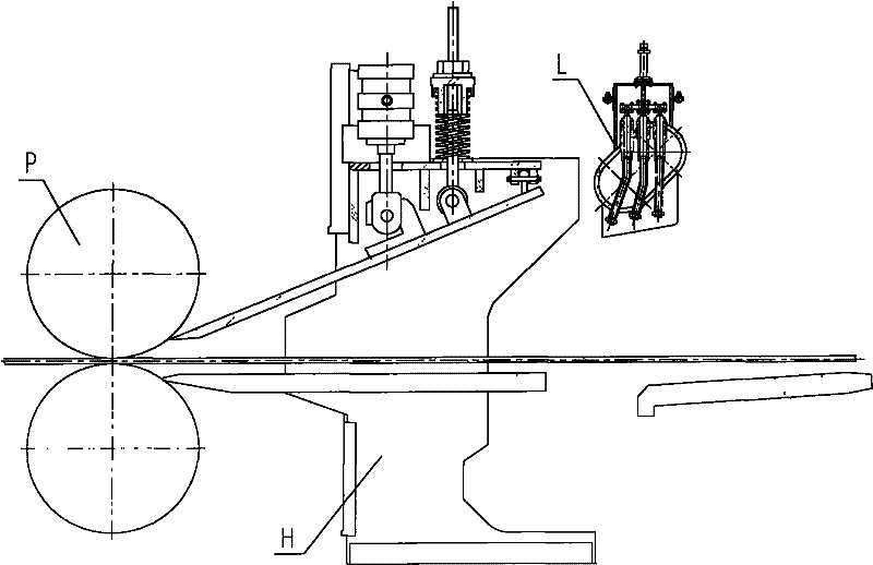
[0035] like figure 1 , the upper spray cooling device L installed between the finishing stands is set above the strip on the entrance side of the finishing stand H, and the cooled strip is formed under the rolling of the roll P.

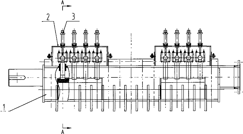
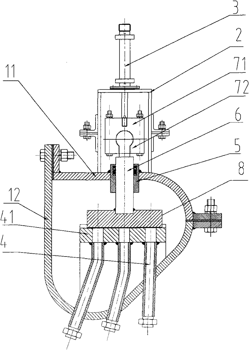
[0036] like figure 2 and image 3 As shown, the upper spray cooling device between the finishing stands includes a split header 1, including a lower tube body 12 and an upper tube cover 11 fixedly and sealingly connected with it. The header pipe 1 is set along the running direction of the vertical steel strip, and a number of discharge pipes are evenly distributed on it along the axial direction of the header pipe 1, and each row of nozzle pipes includes three nozzle pipes 4, and these three nozzle pipes 1. Arranged in the radial direction, the three nozzles 4 are connected to the header 1 through their upper ports, and the upper ports...


PUM


Abstract

The invention discloses an upper spray cooling device arranged among finishing mill racks. The device is arranged above strip steel and at an inlet side of a finishing mill rack. The device comprises a split-type collecting pipe, a plurality of rows of spray pipes, a plurality of opening and closing values and a plurality of driving devices, wherein the split-type collecting pipe is arranged perpendicular to the operating direction of the steel strip; the spray pipes are uniformly arranged along the axial direction of the collecting pipe, each row of spray pipes comprises a plurality of spray pipes arranged along the radial direction of the collecting pipe, and the spray pipes are communicated with the collecting pipe through the upper ports of the spray pipes; the opening and closing values are correspondingly arranged above the plurality of rows of spray pipes and vertically move to break the upper ports of the plurality of rows of spray pipes; and the driving devices are fixedly arranged in a plurality of supports on the split-type collecting pipe, respectively and correspondingly arranged above the plurality of opening and closing values and correspondingly connected with the plurality of opening and closing values so as to realize the driving motion on the opening and closing values. The upper spray cooling of the finishing mill rack has a simple structure, and meanwhile, the adjustment of cooling water along the width direction of the strip steel can be realized.

Description

technical field [0001] The invention relates to a cooling device arranged between finish rolling stands, in particular to an upper spray cooling device with adjustable cooling water width in the hot rolling cooling process. Background technique [0002] The finishing rolling production line of iron and steel enterprises must use the strip cooling device. Its main function is to rapidly cool the finishing strip according to the set finishing target temperature to ensure the product organization and performance of the strip. [0003] With the continuous development of metallurgical production technology, the types and specifications of strip steel have gradually expanded, and microalloy steel and carbon-manganese steel have replaced ordinary steel to become the main products. With the continuous expansion of the rolling specifications of the rolling line and the continuous improvement of the user's product quality requirements, the existing strip steel cooling device can no lo...

Claims


Application Information

Patent Timeline
Patent Type & Authority Applications(China)
IPC IPC(8): B21B45/02
Inventor 王军杨玉芳邹建明钮国卫
Owner BAOSHAN IRON & STEEL CO LTD
Why Eureka
Try Eureka