Eureka AIR delivers breakthrough ideas for toughest innovation challenges, trusted by R&D personnel around the world.

High-straight-edge splint-type bending correction mould

A splint-type, bending technology, applied in the direction of forming tools, manufacturing tools, metal processing equipment, etc., can solve the problems of high non-perpendicularity and appearance requirements, difficult to meet requirements, long period of replacement of molds and debugging, and high requirements for workers' skills, reducing equipment. Investment cost, bottom leveling, the effect of improving product quality

Active Publication Date: 2011-09-21
QINGDAO HOSEN HEAVY IND
View PDF5 Cites 5 Cited by
  • Summary
  • Abstract
  • Description
  • Claims
  • Application Information

AI Technical Summary

Problems solved by technology

[0002] At present, hydraulic or mechanical bending machines are generally used for bending long metal workpieces in China. The disadvantages of using bending machines are: 1) poor versatility of equipment; low efficiency, high cost, low precision, and large floor space; 2) The angle, non-perpendicularity and appearance requirements of the workpiece are high and difficult to meet the requirements; 3) The operation requires high skill of the workers, and the replacement mold debugging cycle is long

Method used


Image

  • High-straight-edge splint-type bending correction mould
  • High-straight-edge splint-type bending correction mould
  • High-straight-edge splint-type bending correction mould

Examples


Embodiment Construction

[0024] The following will be further described in conjunction with the accompanying drawings, not to limit the scope of the present invention.

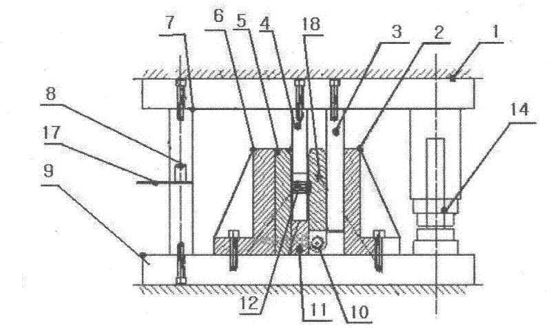
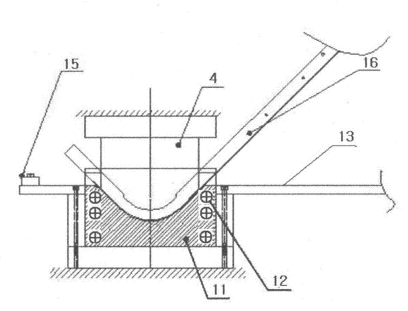
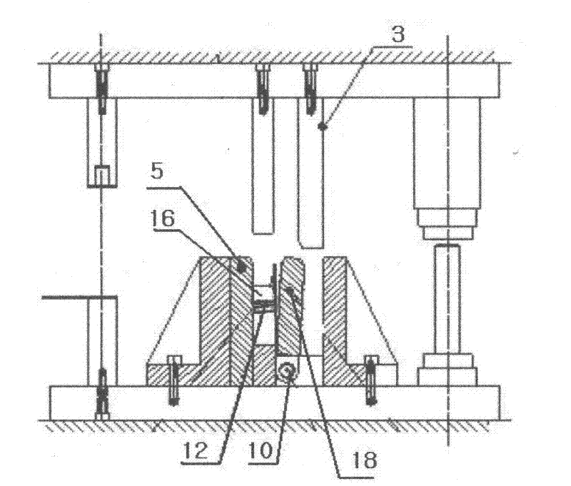
[0025] see figure 1 and figure 2 As shown, the present invention includes an upper template 1 and a lower template 9, on which the upper template 1 is fixed with a punch 4, a wedge 3 and a stop block 7, and on the lower template 9, a pin 10 and a die 11 are arranged , on the pin 10 is provided with an opening and closing splint 18, the opening and closing splint 18 can rotate around the pin shaft 10, and one side of the die 11 is provided with a fixed splint 5, and the fixed splint 5 is fixed on the lower template 9. A baffle 6 is arranged on one side of the fixing splint 5 . A bottom mark pin 8 is arranged on the limit block 7 to control the bottom limit condition of the punch 4 . A spring 12 is provided inside the die 11 . A support plate 13 is provided on the side of the die 11 , and a positioning block 15 is provided at one e...


PUM


Abstract

The invention relates to a high-straight-edge splint-type bending correction mould which comprises an upper template and a lower template; a male mould, a tapered wedge and a limit block are fixed on the upper template; a pin shaft and a female mould are arranged on the lower template; an open and close splint is arranged on the pin shaft; and one side of the female mould is provided with a fixedsplint which is fixed on the lower template. According to the bending correction mould disclosed by the invention, the working efficiency and precision can be improved; the investment cost of equipment is reduced; the utilization rate of the equipment is improved; and the mould is tightly locked with the splint through the tapered wedge so that the plastic deformation of materials can be restrained, and a workpiece is fetched and placed conveniently; a bottom touching correction method is adopted so that the workpiece has stable angle and flat bottom.

Description

technical field [0001] The invention relates to a mold, in particular to a high straight side splint type correction bending mold. Background technique [0002] At present, hydraulic or mechanical bending machines are generally used for bending long metal workpieces in China. The disadvantages of using bending machines are: 1) poor versatility of equipment; low efficiency, high cost, low precision, and large floor space; 2) The angle, non-perpendicularity and appearance of the workpiece are high and difficult to meet the requirements; 3) The operation requires high skill of the workers, and the replacement mold debugging cycle is long. Contents of the invention [0003] The present invention overcomes the deficiencies of the prior art, and proposes a high straight-side splint type correction bending mold, which can be used universally in the field of bending, has a small footprint, low mold cost, high work efficiency, and good product quality , The angle is stable and pra...

Claims


Application Information

Patent Timeline
Patent Type & Authority Applications(China)
IPC IPC(8): B21D37/10
Inventor 王起森仕玉福
Owner QINGDAO HOSEN HEAVY IND
Why Eureka
Eureka Blog
Learn More