
Pneumatic tire

A technology for pneumatic tires and tires, applied in tire parts, tire tread/tread pattern, transportation and packaging, etc., to reduce ground pressure, suppress uneven wear, and improve handling stability.

Inactive Publication Date: 2015-01-21
SUMITOMO RUBBER IND LTD
View PDF8 Cites 0 Cited by
  • Summary
  • Abstract
  • Description
  • Claims
  • Application Information

AI Technical Summary

Problems solved by technology

[0003]However, the above-mentioned methods all have the problem that the drainage performance, especially the water film effect performance, decreases with the decrease of the ditch volume
In this way, the improvement of the steering stability due to the high rigidity of the block and the drainage performance are in an antinomy relationship, so it is very difficult to achieve a balance between the two.

Method used


Image

  • Pneumatic tire
  • Pneumatic tire
  • Pneumatic tire

Examples


Embodiment

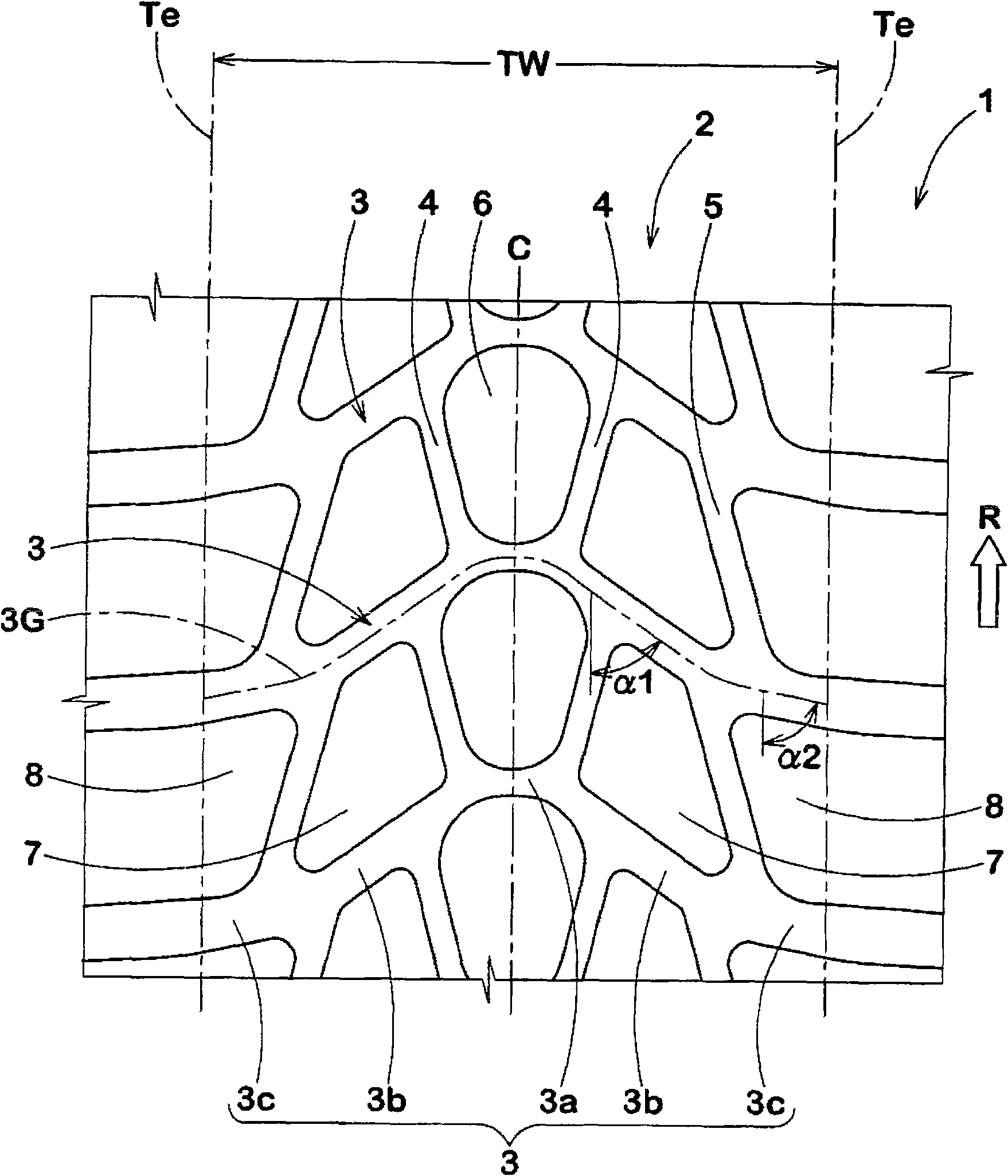
[0065] In order to confirm the effects of the present invention, the specifications based on Table 1 were trial-manufactured with figure 1 Pneumatic tires (10×4.50-5 for front wheels, 11×7.10-5 for rear wheels) for racing cars with a tread portion. And various properties were tested on them. The specific dimensions are as follows. Here, all the specifications are the same except for the specifications shown in Table 1.

[0066] (front wheel / rear wheel)

[0067] Main inclined groove:

[0068] Groove width W3c of the central part: 3.5-4.5mm / 4.0-5.0mm

[0069] Groove width W3m in the middle part: 5.5-6.5mm / 9.0-10.0mm

[0070] Groove width W3s of tire shoulder: 7.5~9.0mm / 10.5~11.5mm

[0071] Angle of the central part relative to the tire circumferential direction: 60-90 degrees / 70-90 degrees

[0072] Angle α1 of the middle part relative to the tire circumferential direction: 55 degrees / 60 degrees

[0073] The angle α2 of the tire shoulder at the ground contact point relat...


PUM


Abstract

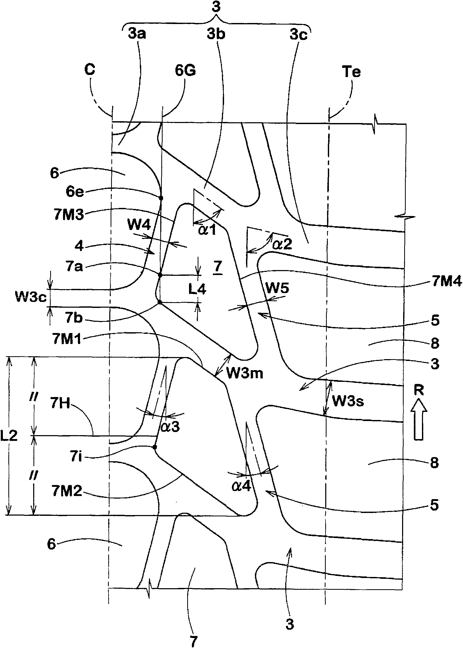
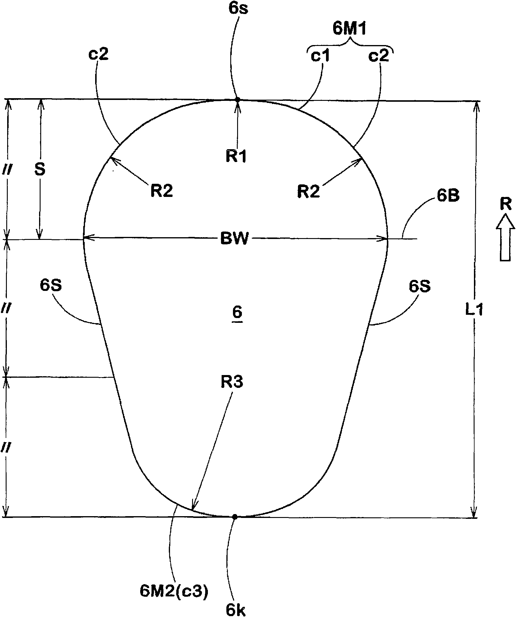
The invention relates to a pneumatic tire, which keeps the drainage through improving the tread shape and improves the operation stability as well as the uneven wearability. The tread part of the pneumatic tire (1) with pointed rotating direction comprises a crown pattern block (6), a pair of middle pattern blocks (7) and a pair of shoulder pattern blocks (8), wherein the crown pattern block (6) is formed by a pair of inside connection ditches (4) and a main tilting ditch (3); the pair of middle pattern blocks (7) is formed by the inside connection ditch, an outside connection ditch (5) and the main tilting ditch; and the pair of shoulder pattern blocks (8) is formed by the outside connection ditch, a grounding terminal (Te) and the main tilting ditch. The tire axial outermost end (6e) of the crown pattern block is located at 0.1-10.0mm position of the tire axial outside than the tire axial innermost end (7i) of the middle pattern block adjacent to the crown pattern block. Furthermore, the position (6B), which the tire axial width of the crown pattern block is the biggest width (BW), is formed in the firstly landing side area (S); and the distance between the firstly landing side area (S) and the end part (6s) of the firstly landing side of the tire rotating direction of the crown pattern block is 1 / 3 of the tire circumferential length (L1) of the crown pattern block.

Description

technical field [0001] The present invention relates to a pneumatic tire that suppresses a decrease in water drainage and improves steering stability and uneven wear by improving grooves and block shapes of a tread portion. Background technique [0002] There is known a pneumatic tire having a block pattern in which a plurality of blocks are formed on a tread portion. In such a pneumatic tire, improvement in steering stability performance and wear resistance is achieved by increasing the rigidity of the blocks. In order to increase the rigidity of the block, methods such as increasing the land ratio, forming a gentle slope on the wall surface of the block, and reducing the groove depth of the tread portion are known. [0003] However, each of the above-mentioned methods has the problem that the drainage performance, especially the water film effect performance, decreases with the decrease of the groove volume. In this way, the improvement of the steering stability due to ...

Claims


Application Information

Patent Timeline
Patent Type & Authority Patents(China)
IPC IPC(8): B60C11/03B60C11/117
CPCB60C11/11B60C11/12
Inventor 藤田将之
Owner SUMITOMO RUBBER IND LTD
Learn More