Crane

A crane and hoisting hook technology, applied in the field of lattice boom cranes and hoisting hooks, can solve the problems of huge equipment costs and operating costs, etc.

Active Publication Date: 2011-09-21
LIEBHERR WERK EHINGEN
View PDF4 Cites 6 Cited by
  • Summary
  • Abstract
  • Description
  • Claims
  • Application Information

AI Technical Summary

Problems solved by technology

[0004] The development of this type of lifting system was aimed at extending the maximum permissible limit value of the wind speed, since each individual lifting or each installation entails enormous equipment and operating costs

Method used


Image

  • Crane
  • Crane
  • Crane

Examples


Embodiment Construction

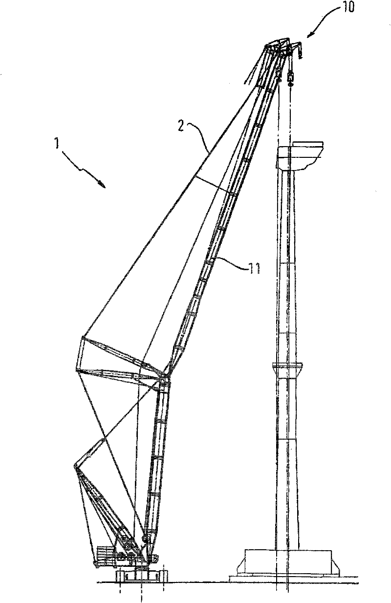
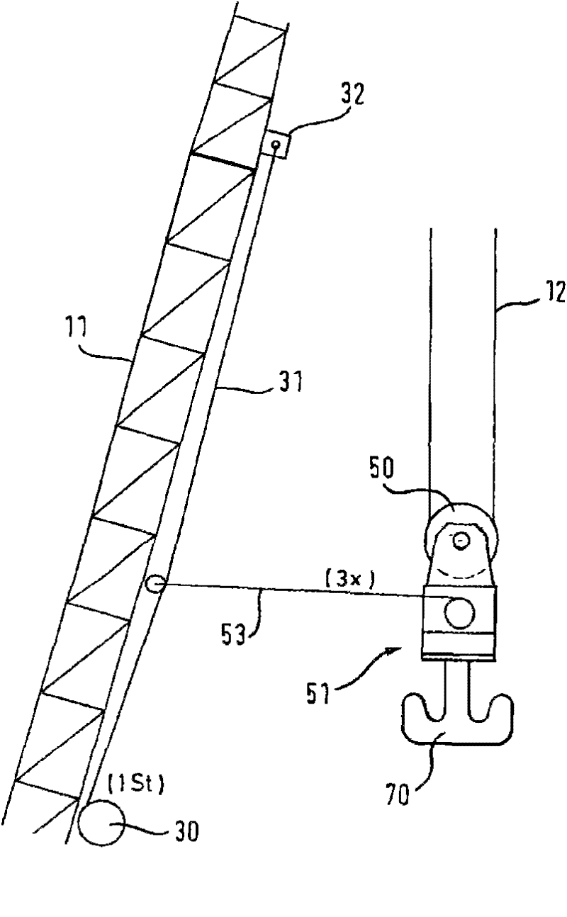
[0069] exist figure 1 The lattice jib crane 1 shown in FIG. 2 has a two-part jib 11 in a manner known per se, which can be lifted about a horizontal jib axis by means of a jib device. The reference numbers used below refer only to figure 1to 3. Behind the main boom 11 is mounted a rearwardly oriented chevron boom. The boom 11 is tensioned by means of a tensioning rod 2 .

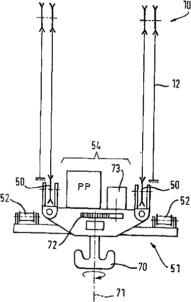
[0070] At least one hoisting cable 12 is guided through the tip of the boom 11 via one or more deflection pulleys of the pulley head 10 and is threaded multiple times into the deflection pulleys 50 of the hook block 51 . In order to be able to better absorb the forces caused by the load and its orientation about the vertical axis, the pulley top 10 is designed to expand at the tip of the crane jib 11 . Depending on the design of the pulley head 10 , the deflection pulleys 50 of the hook block 51 are correspondingly arranged at a distance from one another, so that an almost vertical distribution of the ho...


PUM


Abstract

The invention relates to a crane, in particular to a truss arm type crane, comprising a hook pulley set. The hook pulley set comprises a lifting device, especially a hoisting hook, wherein the hook pulley set comprises at least one winch; a control rope released by the winch and the arm of the crane are connected or can be connected so as to protect and / or orient the position of cargos or the position of the hook pulley set.

Description

technical field [0001] The invention relates to a crane, in particular a lattice jib crane, which has a hook block with a cargo lifting device, in particular a lifting hook. Background technique [0002] When lifting large loads at high heights, the stability of the lifting system against external influences, in particular acting wind forces, plays a decisive role. Large goods to be lifted have a large area and thus provide a large surface area for the wind force to act on. The applied forces cause swaying of the load or cause swinging of the hook, which can result in an unstable lifting system. For safety reasons, a limit value for the maximum permissible wind speed is defined until this limit value allows the planned lift to be fully realized. [0003] The stability of the system with respect to the acting wind forces is also a decisive criterion when installing lifted goods at high altitudes, since it is desirable that the goods be aligned as precisely and stably as pos...

Claims


Application Information

Patent Timeline
Patent Type & Authority Applications(China)
IPC IPC(8): B66C23/62
CPCB66C23/185B66C13/06
Inventor 汉斯-迪特尔·维利姆格韦·里希特
Owner LIEBHERR WERK EHINGEN
Why Eureka
Try Eureka