Roller for inhibiting vibration and method thereof

A technology of rollers and roller sleeves, applied in the directions of shafts and bearings, textiles and papermaking, papermaking machines, etc., can solve the problems of expensive application, inability to adjust the deflection in a targeted manner, large structure and manufacturing technology, etc.

Inactive Publication Date: 2011-09-21
VOITH PATENT GMBH
View PDF4 Cites 1 Cited by
  • Summary
  • Abstract
  • Description
  • Claims
  • Application Information

AI Technical Summary

Problems solved by technology

However, this application is expensive and requires a great deal of effort in terms of construction and production technology
No targeted adjustment of the deflection is possible with this type of roller

Method used


Image

  • Roller for inhibiting vibration and method thereof
  • Roller for inhibiting vibration and method thereof
  • Roller for inhibiting vibration and method thereof

Examples


Embodiment Construction

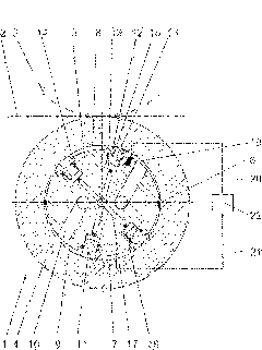
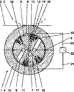
[0033] exist figure 1 , a section of the roller 1 according to the invention can be seen. The rollers work together with a pair of rollers 3, shown in dashed lines, in order to process the fibrous web 2, also shown in dashed lines, in the so-called nip between them.

[0034]The roller 1 has a rotating sleeve 4 and a stationary shaft 5 . A longitudinal seal 6 is arranged between the sleeve and the shaft, which longitudinal seal 6 divides the annular chamber 7 into an upper chamber 8 and a lower chamber 9 . The two chambers are filled with pressurized fluid, typically oil, at different pressures. The channel 10 is designed as a channel for the chambers 8 , 9 to input or output pressure fluid. The different pressures in the chambers 8 and 9 enable the roll 1 to bend in accordance with the counterpart roll 3 . For various reasons, eg an uneven fiber web to be treated or an out-of-round roll, the system consisting of roll 1 and counter roll 3 is prone to vibrations. Such vibra...


PUM


Abstract

The invention relates to a roller, comprising an annular hollow roller sleeve (4) supported on an anti-torsion shaft (5), for processing a fibre amplitude surface (2) and forming a roller clearance together with a matching roller (3), wherein an annular cavity between the roller sleeve (4) and the shaft (5) is divided into at least two chambers (8, 9) filled with pressure fluids of different pressures so as to reach roller expectation deflection through at least two axial sealing pieces (6). To reduce vibration of the roller sleeve in operation, pressure is applied on the roller sleeve (4) through at least one actuator (11) supported on the shaft.

Description

technical field [0001] The invention relates to a roll having an annular hollow roll sleeve supported on a torsion-resistant shaft, which can form a nip with counter-rollers for the treatment of the fibrous web, wherein the gap between the roll sleeve and the shaft is The annular cavity is divided by at least two axial seals into at least two chambers which can be filled with pressure fluids of different pressures to obtain the desired roll deflection. [0002] Furthermore, the invention relates to a method for damping vibrations in a system consisting of the roller and the counter-roller. Background technique [0003] Accordingly, the rolls are rolls known in the professional field as "dance rolls" or "S-rolls". Today, such rolls are commonly used in calenders that are narrow (relative to the width of the web). The different pressures in the two chambers are sufficient to achieve a deflection substantially commensurate with the bending of the mating rollers. [0004] In ...

Claims


Application Information

Patent Timeline
IPC IPC(8): D21G1/02
CPCD21G1/008D21G1/022F16C13/026
Inventor 乔切恩·尼曼拉斯·克鲁格
Owner VOITH PATENT GMBH
Why Eureka
Try Eureka