Top beam of hydraulic support

A technology of hydraulic support and roof beam, which is applied in the direction of supporting the roof beam of the mine roof, mining equipment, earth square drilling and mining, etc., can solve the problem of affecting the unit and pedestrian passage space, which can not be solved well and cannot be kept constant Resistance support and other issues, to achieve the effect of weight reduction, small impact, and improved support resistance

Inactive Publication Date: 2014-12-31
李泽宇
View PDF5 Cites 0 Cited by
  • Summary
  • Abstract
  • Description
  • Claims
  • Application Information

AI Technical Summary

Problems solved by technology

The roof connection performance of the wedge-shaped roof beam has been improved, but the roof beam of the wedge-shaped roof beam uses the principle of self-locking friction between components, so it cannot be supported by constant resistance
The articulated top beam can achieve constant resistance support, but because the front beam jack is horizontally arranged below the top beam near the hinge point, two problems arise: one problem is the vertical line between the hinge point and the center line of the front beam jack The distance is too close, so the front beam jack must have enough support and connection strength
The second problem is that the front beam jack is horizontally arranged under the top beam, which affects the passage space of the unit and pedestrians. In order to solve this problem, the front beam jack needs to be moved upwards
Since the solutions to these two problems are contradictory, they have not been better resolved for decades.

Method used


Image

  • Top beam of hydraulic support
  • Top beam of hydraulic support
  • Top beam of hydraulic support

Examples


Embodiment approach

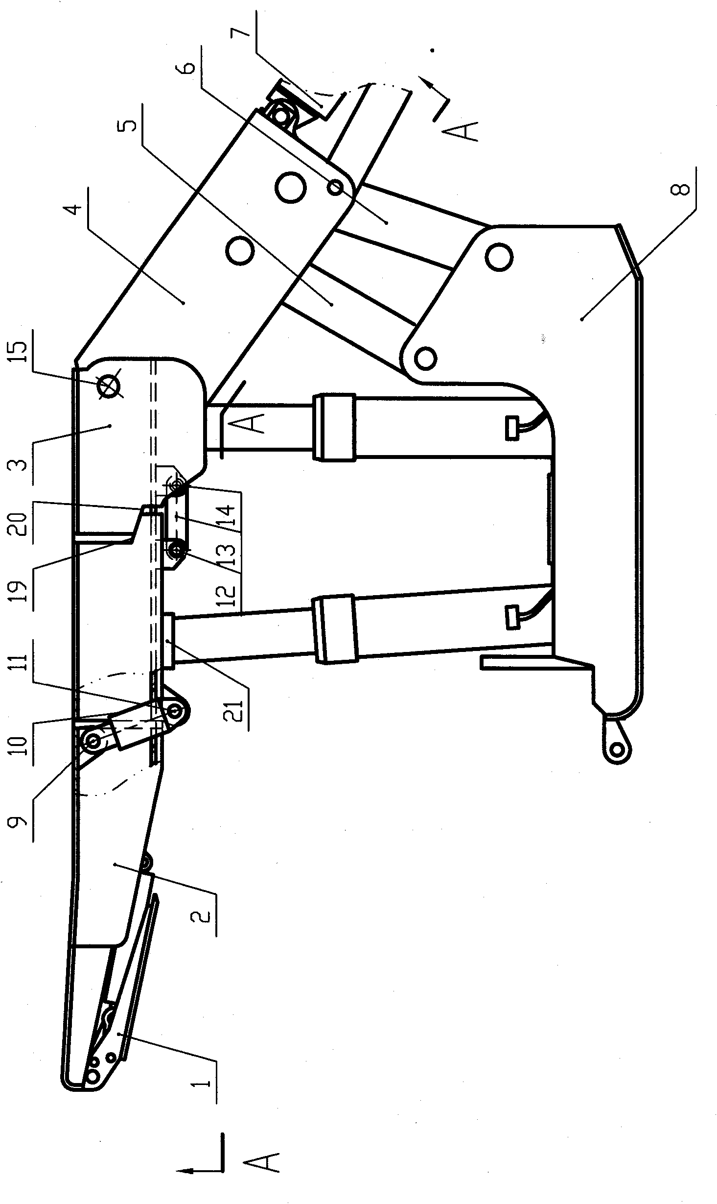
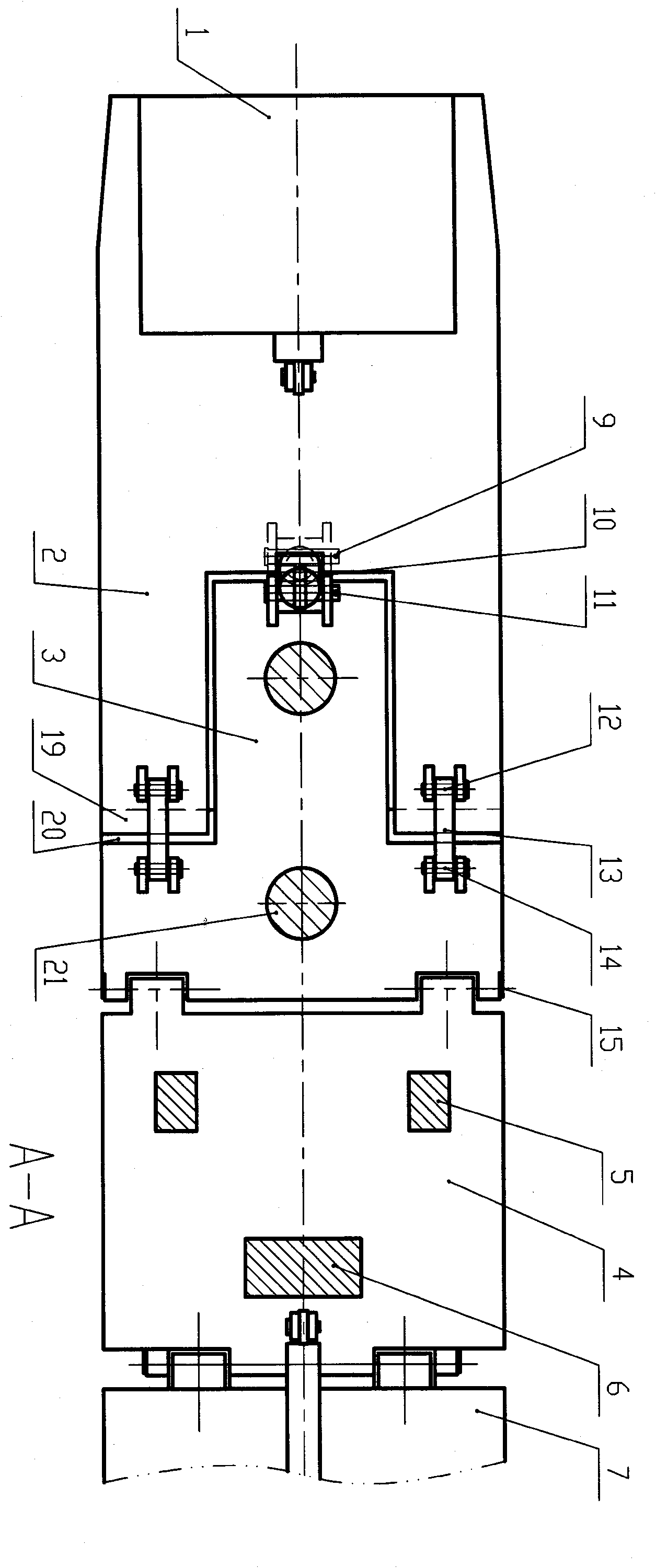
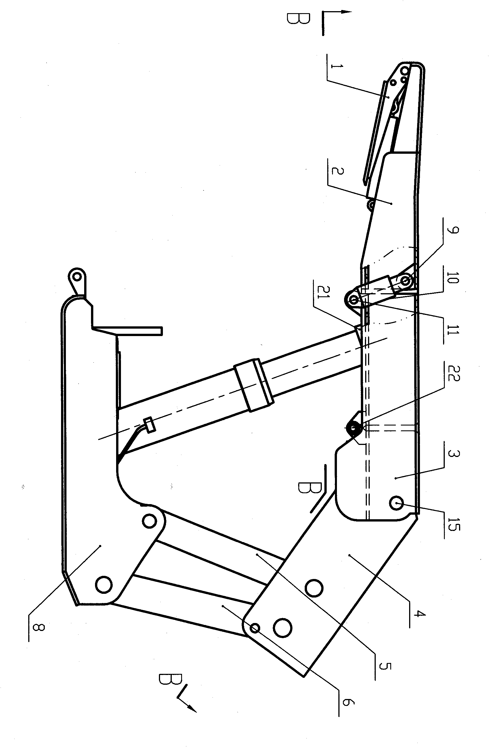
[0022] combine figure 1 and figure 2 , the first embodiment of the top beam of the hydraulic support of the present invention is to apply the present invention to another purchased patent belonging to the supporting shield type hydraulic support. Of course, it can also be applied to the common four-column support shielding hydraulic support. Concave auxiliary top beam body 2 without column socket 21 including front end hinged forward beam; convex main top beam body with column socket 21 matching with the concave part of auxiliary top beam body 2 3. The auxiliary top beam body 2 and the main top beam body 3 are inlaid together to form a top beam; the front beam jack 10 is hinged with the auxiliary top beam body 2 through the pin 9, and hinged with the main top beam body 3 through the pin 11; 12 is hinged with the auxiliary top beam body 2 and two connecting rods 13 hinged with the main top beam body 3 through the pin 14; the column socket 21 for connecting the hydraulic prop...


PUM


Abstract

The invention discloses a top beam of a hydraulic support, which is used for a coal mining face under a coal mime shaft. The top beam comprises an auxiliary top beam body 2, a main top beam body 3, a front beam lifting jack 10, a needling 21, a connecting device and an articulated hole 15, wherein the front beam lifting jack 10 is articulated between the auxiliary top beam body 2 and the main top beam body 3; the needling 21 is used for installing the hydraulic support; the connecting device is used for installing a front extension beam 1; and the articulated hole 15 is used for installing a shielding beam or a rock retaining device 4. As the auxiliary top beam body 22 can float up and down relative to the main top beam body 3, the top filing is good; as the front beam lifting jack is arranged in the top and bottom direction, few passing space can be occupied; and the auxiliary top beam body 2 and the main top beam body 3 adopt inlaid structures so that the supporting resistance of the auxiliary top beam body 2 can be increased. The top beam disclosed by the invention is particularly suitable for being used in a working surface of an uneven top plate.

Description

technical field [0001] The invention relates to a top beam of a hydraulic support used for supporting a top plate in an underground coal mining working face of a coal mine. Background technique [0002] Hydraulic supports are divided into two categories: fully mechanized mining supports and sliding supports. The background technology of the present invention includes the top beams in these two types of hydraulic supports. In order to overcome the shortcomings of the above two types of supports, the applicant once designed a chain suspension hydraulic support (Chinese patent application number ZL200520019152.2). It is integral, so when the uneven roof is supported, the bending moment on the top beam is relatively large, so when the support resistance is large, the top beam is heavy. In addition, the top performance is not good. [0003] The top beam of the fully mechanized mining support has three types: integral type, hinged type and wedge-shaped structure. (see Wang Guof...

Claims


Application Information

Patent Timeline
Patent Type & Authority Patents(China)
IPC IPC(8): E21D17/00
Inventor 李泽宇
Owner 李泽宇
Why Eureka
Try Eureka