Distributor, and evaporator and refrigerating machine with the same

A distributor and evaporator technology, used in evaporators/condensers, refrigerators, refrigeration components, etc., can solve the problems of evaporator heat transfer efficiency and heat exchange performance decline, cycle expansion, and compressor performance decline. The effect of improving heat transfer efficiency and heat exchange performance, improving performance and efficiency, preventing performance degradation

Inactive Publication Date: 2011-09-21
LG ELECTRONICS INC
View PDF7 Cites 21 Cited by
  • Summary
  • Abstract
  • Description
  • Claims
  • Application Information

AI Technical Summary

Problems solved by technology

Therefore, the flow of the cooling medium is in an unstable state, and the circulation is significantly enlarged
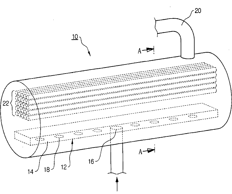
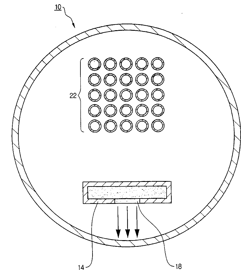
[0009] In addition, since the center of the distribution pipe 18 faces the bottom of the evaporator directly downward in the vertical direction, when the cooling medium hits the bottom of the evaporator, the impact of the collision becomes significant, and the liquid level of the cooling medium of the evaporator will be excessively volatile
During the suction of the cooling medium liquid and the bubbling liquid through the suction pipe 20, the suction of the liquid in the compressor causes the performance of the compressor to decrease.
Moreover, due to the generation of foam on the liquid surface of the cooling medium, the heat transfer efficiency and heat exchange performance of the evaporator are further reduced
[0010] Therefore, in the existing distributor, the heat transfer efficiency and heat exchange performance of the evaporator are lowered due to the structural problems as described above, and the performance of the compressor is lowered due to the excessive generation of foam and the phenomenon of liquid suction.
Therefore, it is difficult to improve the efficiency and performance of the refrigerator

Method used


Image

  • Distributor, and evaporator and refrigerating machine with the same
  • Distributor, and evaporator and refrigerating machine with the same
  • Distributor, and evaporator and refrigerating machine with the same

Examples


Embodiment Construction

[0025] Hereinafter, exemplary embodiments will be described more fully with reference to the accompanying drawings that illustrate the exemplary embodiments. This invention may, however, be embodied in many different forms and should not be construed as limited to those exemplary embodiments set forth herein. Rather, these exemplary embodiments are provided so that this disclosure will be thorough and complete, and will fully convey the scope of the invention to those skilled in the art. In the description, details of well-known features and techniques may be omitted to avoid unnecessarily obscuring the provided embodiments.

[0026] Unless otherwise defined, the terms (including technical and scientific terms) used herein have the same meaning as commonly understood by one of ordinary skill in the art. It should also be understood that terms (eg, terms defined in commonly used dictionaries) should be interpreted as having meanings consistent with their meanings in the relate...


PUM


Abstract

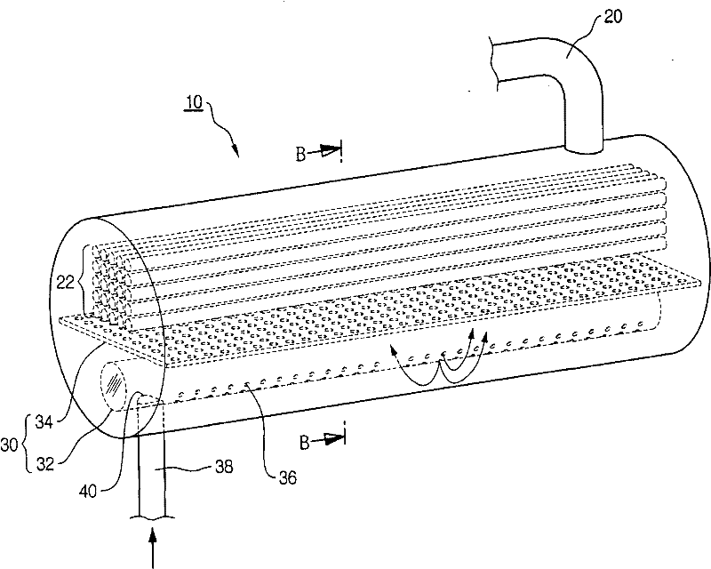
Provided are a distributor having a distribution tube having an inner surface formed as a curved surface, a plurality of distribution holes which are formed in a lower semicircular region of the distribution tube with respect to a horizontal line of the distribution tube and are arranged to be symmetrical about a vertical line of the distribution tube and a connection hole provided in the distribution tube so that the distribution tube is connected to a connection tube, an evaporator and a refrigerating machine with the distributor. A perforated plate may be fixed to an inside of the distribution tube so as to block a flow path of a cooling medium. The distributor is capable of forming a stable flow and a steady circulation while a cooling medium flows from a condenser into an evaporator and a steady circulation are formed and spread uniformly and supplied tp the evaporator.

Description

technical field [0001] The present invention relates to a distributor, an evaporator and a refrigerating machine having the distributor, and more particularly to an improved distributor for forming a smooth flow and a stable circulation of the cooling medium when flowing from the condenser into the evaporator , and the evaporator and refrigerator with this distributor. Background technique [0002] Generally, a vapor compression refrigerator consists of a compressor, condenser, expansion valve, and evaporator. The refrigeration cycle of this vapor compression refrigerator can be roughly described as: the gaseous cooling medium is compressed by the compressor to a relatively high pressure, and is supplied to the condenser, releases heat, and is subsequently condensed into a liquid state. [0003] The condensed liquid cooling medium flowing through the expansion valve (usually through the expansion valve, capillary, orifice, expansion turbine, etc.) is throttled to a relative...

Claims


Application Information

Patent Timeline
Patent Type & Authority Applications(China)
IPC IPC(8): F25B39/02F28F9/22F28F27/02F25B1/00
CPCF25B39/028F28F9/0273F28D7/163F25B2339/0242F28D2021/0071F28F9/0278
Inventor 李亨濬
Owner LG ELECTRONICS INC
Why Eureka
Try Eureka