
Sensing and driving device, touch sensing system and sensing and driving method

A driving device and touch sensing technology, applied in the field of driving device, driving method and touch sensing system, can solve the problems of sensing circuit output voltage offset, compressing the sensing range of sensing circuit, etc., and achieve optimal sensing The effect of measuring acuity

Active Publication Date: 2015-11-25
NOVATEK MICROELECTRONICS CORP
View PDF3 Cites 0 Cited by
  • Summary
  • Abstract
  • Description
  • Claims
  • Application Information

AI Technical Summary

Problems solved by technology

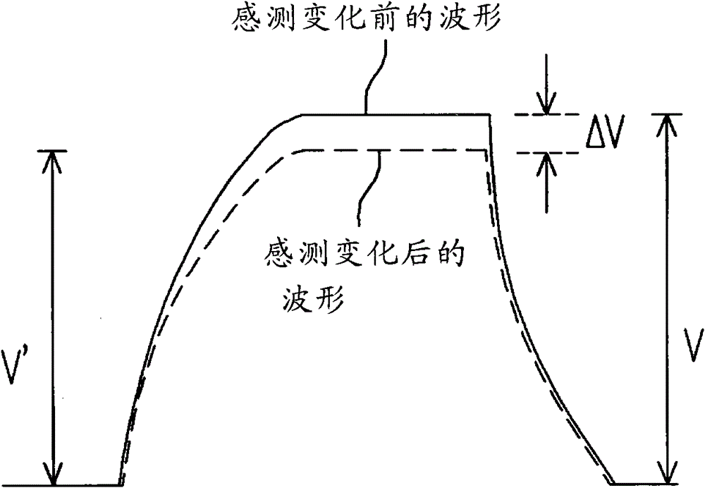
Since the common mode voltage will cause the offset of the output voltage of the sensing circuit, it will compress the sensing range of the sensing circuit

Method used


Image

  • Sensing and driving device, touch sensing system and sensing and driving method
  • Sensing and driving device, touch sensing system and sensing and driving method
  • Sensing and driving device, touch sensing system and sensing and driving method

Examples


Embodiment Construction

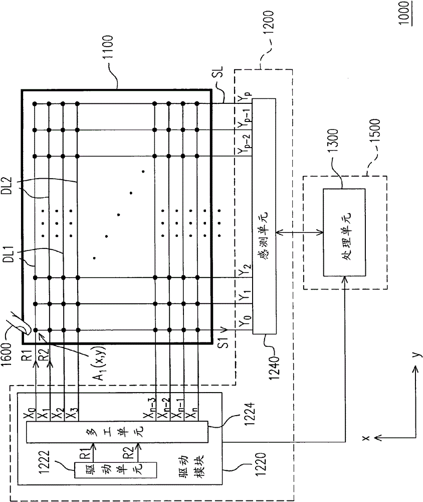
[0042] figure 2 It is a touch sensing system 1000 according to an embodiment of the present invention. Please refer to figure 2 , the touch sensing system 1000 includes a sensing interface 1100 , a sensing driving device 1200 and a processing unit 1300 . The sensing interface 1100 includes at least one driving line DL1 and at least one driving line DL2 , and the driving line DL1 and the driving line DL2 are respectively two adjacent driving lines on the sensing interface 1100 . Besides, the sensing interface 1100 also includes a plurality of sensing lines SL. In this embodiment, the sensing interface 1100 is, for example, a touch panel of a touch display or other touch pads with a touch sensing function.

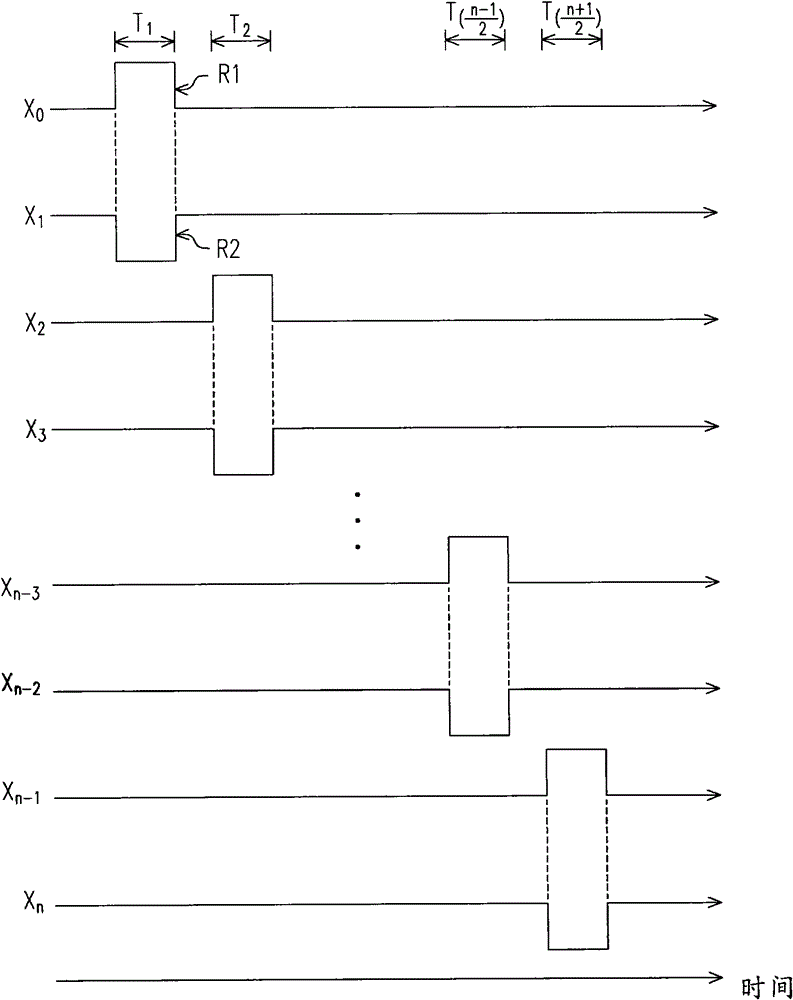
[0043] Such as figure 2 As shown, the sensing and driving device 1200 is coupled to the sensing interface 1100 and includes a driving module 1220 and a sensing unit 1240 . The driving module 1220 is adapted to output the reference signal R1 and the reference signal R...


PUM


Abstract

The invention provides a sensing driving device, a touch sensing system and a sensing driving method, which are suitable for a sensing interface. The sensing driving device comprises a driving module and a sensing unit. The driving module is used for outputting a first reference signal and a second reference signal which have opposite polarities during a first period and respectively transmitting the first reference signal and the second reference signal to a first driving wire and a second driving wire of the sensing interface so as to generate a first sensing signal. The sensing unit is used for receiving the first sensing signal and detecting the variation of the first sensing signal so as to generate a sensing result.

Description

technical field [0001] The present invention relates to a driving device, a driving method and a touch sensing system, and in particular to a touch sensing system, a sensing driving device and a sensing driving method for the touch sensing system. Background technique [0002] Currently, touch panels can be roughly classified into resistive, capacitive, infrared and ultrasonic touch panels, among which resistive touch panels and capacitive touch panels are the most common products. Compared with the resistive touch panel which can detect the user's motion only by pressing the panel, the capacitive touch panel can detect the user's motion only by touching or hovering. In the prior art, the capacitive touch panel obtains the touch information of a single point or more than two points by detecting the voltage change on the sensing line. [0003] figure 1 It is a schematic diagram of the waveform of the voltage value of the existing sensing line before and after the induction ...

Claims


Application Information

Patent Timeline
Patent Type & Authority Patents(China)
IPC IPC(8): G06F3/041G06F3/044
Inventor 林清淳邓永佳洪敬和张岑玮林奕良蔡竣杰
Owner NOVATEK MICROELECTRONICS CORP
Learn More