
Filtering device, filtering device and transmission device

A filter device and filter device technology, applied in the fields of filter devices, transmission devices, and filter devices, can solve problems such as excessive common mode current, negative reflection of common mode signals, and narrow filtering frequency range, so as to reduce noise radiated to the outside. , improve the signal-to-noise ratio, good attenuation effect

Pending Publication Date: 2021-12-10
陈继良
View PDF0 Cites 1 Cited by
  • Summary
  • Abstract
  • Description
  • Claims
  • Application Information

AI Technical Summary

Problems solved by technology

This design causes the frequency range of the filter to be too narrow. At the same time, although the common-mode signal reflected by the common-mode inductor is absorbed by the differential-mode inductor, the common-mode signal introduced by the differential signal drive circuit or the differential cable will still reach the common-mode signal along the signal line path. Die inductance
And this part of the common mode signal attenuation is not obvious
[0013] (3) When the common-mode impedance of the differential-mode inductor is much smaller than the common-mode impedance in the signal line, it may cause excessive common-mode current flowing through the differential signal drive circuit or negative reflection of the common-mode signal, resulting in signal drive circuit Abnormal work
[0016] (2) Due to the low impedance characteristics of the differential mode inductor on the right to the common mode signal, the noise on the ground plane is easily coupled to the cable of the signal line in the form of common mode noise

Method used


Image

  • Filtering device, filtering device and transmission device
  • Filtering device, filtering device and transmission device
  • Filtering device, filtering device and transmission device

Examples


Embodiment 1

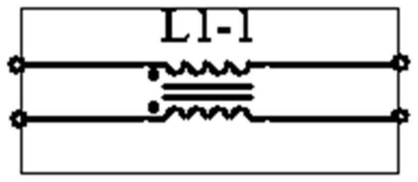
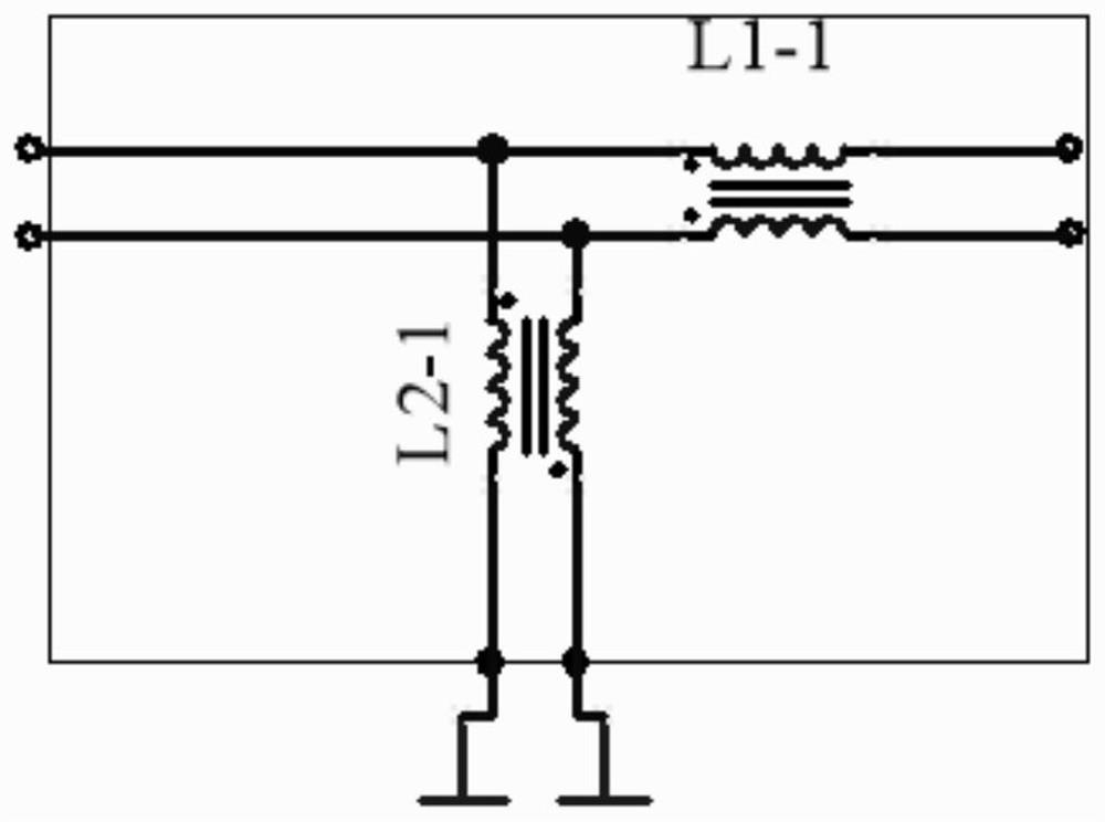
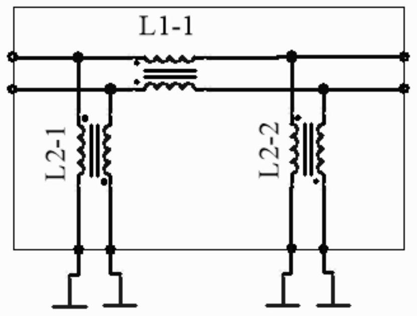
[0120] Embodiment 1 of a filter device is a device composed of two common-mode inductors in series and a differential-mode inductor connected between the differential line and the ground, forming a two-stage cascade filter for the common-mode signal. The effect is better.

[0121] Figure 3A The structure of Embodiment 1 of a filtering device is shown, which includes sequentially connected common-mode inductors L1_1, differential-mode inductors L2_1, and common-mode inductors L1_2, and the magnetic fluxes generated by the common-mode signals of the two coils of each common-mode inductor reinforce each other, The magnetic flux generated by the common mode signal of the two coils of the differential mode inductor cancels each other out. Among them, the two coils of the common mode inductor L1_1 are respectively connected in series with the input terminals 1a and 1b of the device; the two coils of the differential mode inductor L2_1 are respectively connected between the two bra...

Embodiment 2

[0187] Embodiment 2 of a filter device After Embodiment 1 of the filter device, several circuit combinations consisting of a common-mode inductor and a differential-mode inductor are sequentially connected to form a multi-stage cascaded filter for common-mode signals.

[0188] Figure 4A The structure of Embodiment 2 of a filter device is shown, which is formed by sequentially connecting N-1 common-mode inductors and N-1 differential-mode inductors after Embodiment 1 of the filter device. The N-1 common-mode inductors are sequentially connected in series on the differential line, and are respectively numbered L1_3 to L1_N+1, wherein the two coils of each common-mode inductor are respectively connected in series on a branch of the differential line; the N-1 The differential mode inductors are sequentially connected in parallel between the differential line and the ground, and are respectively numbered L2_2 to L2_N, wherein the two coils of each differential mode inductor are re...

Embodiment 3

[0263] Embodiment 3 of a filtering device includes two common-mode inductors in series and two capacitors respectively connected between the two branches of the differential line between them and the ground, forming a secondary cascade connection for the common-mode signal Filtering, and make full use of the frequency characteristics of the combination of multiple inductors and capacitors, the filtering effect is better.

[0264] Figure 6A It shows the circuit structure of Embodiment 3 of a filter device, which includes sequentially connected common-mode inductor L1_1, capacitor C3a, capacitor C3b and common-mode inductor L1_2, when the common-mode signal flows through the two coils of each common-mode inductor The generated magnetic fluxes reinforce each other. Among them, the two coils of the common mode inductor L1_1 are respectively connected in series with the input ends 1a and 1b of the filter device; the two coils of the common mode inductor L1_2 are respectively conn...


PUM


Abstract

The invention provides a filtering device which comprises at least two common mode inductors and at least one differential mode inductor. Each of the common mode inductor and the differential mode inductor is a choking coil with two coils; magnetic fluxes generated when a common-mode signal flows through two coils of the common-mode inductor are mutually enhanced; magnetic fluxes generated when the common-mode signal flows through the two coils of the differential-mode inductor are mutually counteracted; one coil of each common-mode inductor is sequentially connected to one branch of the differential circuit in series, the other coil of each common-mode inductor is sequentially connected to the other branch of the differential circuit in series, and one coil of the two coils of one differential-mode inductor is connected between each of the two branches of the differential circuit between the adjacent common-mode inductors and the ground. The invention also correspondingly provides a filtering device and a transmission device. According to the filtering device, the filtering device and the transmission device, common-mode signal interference is reduced through a cascade filtering method.

Description

technical field [0001] The invention relates to an electronic circuit system, and mainly relates to a filter device, a filter device and a transmission device of a differential line. Background technique [0002] In order to meet the requirements of multi-functionality and high performance in the entire electronic field, the processing speed and transmission speed of data are constantly increasing, and the communication rate requirements between electronic devices are also further improved. With the development of serial bus technology, it has gradually formed its current dominant position in high-speed interfaces. Serial bus technology is used in many standards, such as: universal serial bus, high-speed serial computer expansion bus standard, Ethernet, vehicle Ethernet, low voltage differential signal, high-definition multimedia interface. [0003] Especially with the increase of electronic equipment in the design of automobiles, the application of various data communicati...

Claims


Application Information

Patent Timeline
Patent Type & Authority Applications(China)
IPC IPC(8): H03H7/06H03H7/01
CPCH03H7/06H03H7/01
Inventor 陈继良
Owner 陈继良
Learn More