
Electrocardiograph detection system

A detection system and electrical detection technology, applied in diagnostic recording/measurement, medical science, sensors, etc., can solve problems such as unsatisfactory common-mode rejection ratios, improve CMRR, reduce initial common-mode signals, and reduce human body common-mode signals Effect

Inactive Publication Date: 2017-06-06
SHENZHEN NOVOCARE MEDICAL DEVICES CO INC
View PDF3 Cites 1 Cited by
  • Summary
  • Abstract
  • Description
  • Claims
  • Application Information

AI Technical Summary

Problems solved by technology

However, the common mode rejection ratio still cannot meet people's expectations

Method used


Image

  • Electrocardiograph detection system
  • Electrocardiograph detection system
  • Electrocardiograph detection system

Examples


Embodiment Construction

[0021] Reference will now be made in detail to the exemplary embodiments, examples of which are illustrated in the accompanying drawings. When the following description refers to the accompanying drawings, the same numerals in different drawings refer to the same or similar elements unless otherwise indicated. The implementations described in the following exemplary examples do not represent all implementations consistent with the present disclosure. Rather, they are merely examples of apparatuses and methods consistent with aspects of the present disclosure as recited in the appended claims.

[0022] The terminology used in the present disclosure is for the purpose of describing particular embodiments only and is not intended to limit the present disclosure. As used in this disclosure and the appended claims, the singular forms "a", "the", and "the" are intended to include the plural forms as well, unless the context clearly dictates otherwise. It should also be understood ...


PUM


Abstract

The invention provides an electrocardiograph detection system which comprises a first upper limb electrode, a second upper limb electrode, an un-grounded lower limb flexible electrode, a right leg driving circuit and a differential amplifying circuit, wherein the right leg driving circuit is used for reversely processing common-mode signals from the first upper limb electrode and the second upper limb electrode and then guiding the common-mode signals into the lower limb of a user through the lower limb flexible electrode.

Description

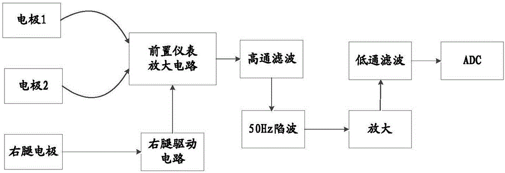
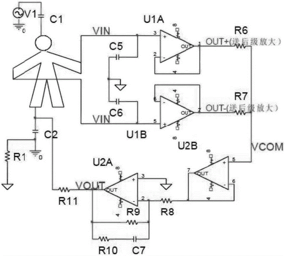
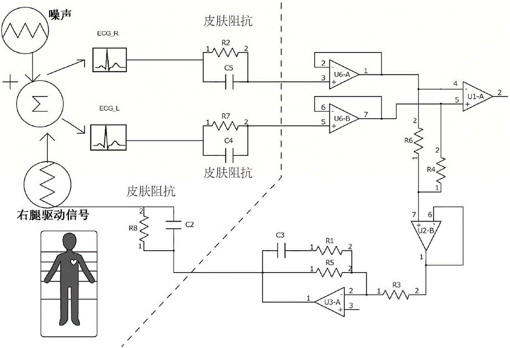
technical field [0001] The present disclosure relates to an electrocardiogram detection system, in particular to an electrocardiogram detection system driven by a right leg. Background technique [0002] The "right leg drive" technology is used in modern ECG detection systems. The left-hand electrode (yellow line) of the lead line is connected to the output terminal of the signal generator, and the right-hand electrode (red line) and the right leg electrode (black line) are short-circuited. Connect to the ground terminal of the signal generator, that is, the electrical signal of the "center electrode" is applied to the human body through the right leg electrode after inversion, so as to achieve the purpose of eliminating common mode interference signals to the greatest extent. [0003] Figure 1A is the block diagram of this "right leg drive" technology. Figure 1B It is usually used to include the circuit diagram of the right leg drive circuit. Usually, the right leg driv...

Claims


Application Information

Patent Timeline
Patent Type & Authority Applications(China)
IPC IPC(8): A61B5/0402A61B5/0408
CPCA61B5/282A61B5/318
Inventor 熊贤志谢静甘健斌邓成坤罗申
Owner SHENZHEN NOVOCARE MEDICAL DEVICES CO INC
Learn More