
Current sensing circuit for pwm applications with pulse width modulation and corresponding current process

Active Publication Date: 2010-03-18
STMICROELECTRONICS SRL
View PDF12 Cites 4 Cited by
  • Summary
  • Abstract
  • Description
  • Claims
  • Application Information

AI Technical Summary

Benefits of technology

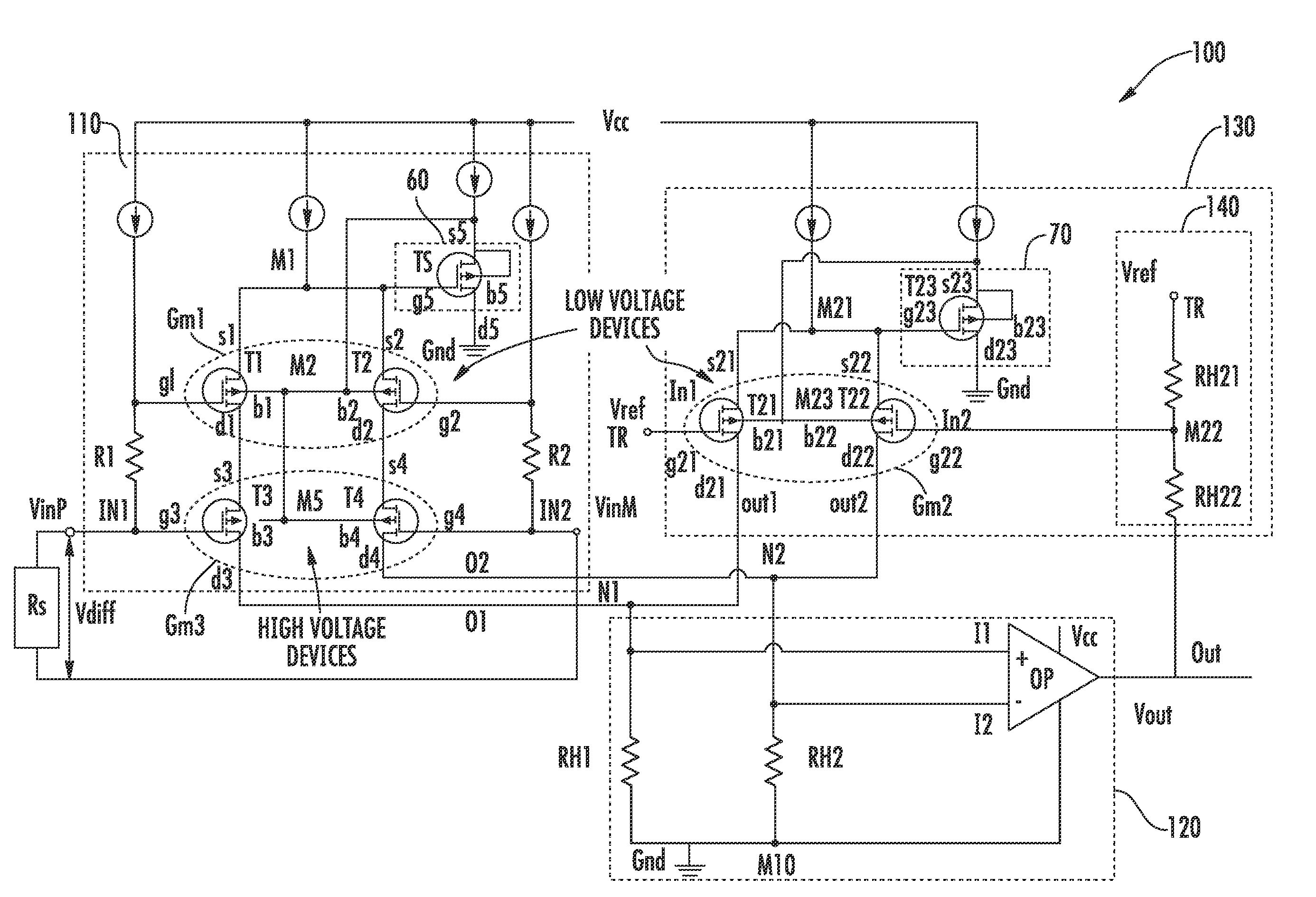
[0034]The advantage of this current sensing circuit lies in the improved CMRR. In fact, the presence of the third transconductance amplifier placed in cascade to the first transconductance amplifier allows balance for the switches of the differential voltage sensed across the sensing resistor.

Problems solved by technology

In fact, as is typical, a low CMRR introduces an additional signal in the current feedback depending on the voltage value of the input common mode and moreover, at the high operation frequencies, the CMRR parameter could reduce the phase margin of the passing band of the device itself, thereby jeopardizing its performance.

Method used


Image

  • Current sensing circuit for pwm applications with pulse width modulation and corresponding current process
  • Current sensing circuit for pwm applications with pulse width modulation and corresponding current process
  • Current sensing circuit for pwm applications with pulse width modulation and corresponding current process

Examples


Embodiment Construction

[0045]More specifically, the present invention relates to a current sensing circuit comprising a first and a second input terminal respectively connected to the ends of a sensing resistor Rs and an output terminal Out suitable for feedback driving a current. The sensing circuit comprises an input block having a first transconductance amplifier powered by a supply voltage and interposed between the first and the second input terminals and first and second internal circuit nodes. The current sensing circuit also includes an amplifier block having an operational amplifier connected to a ground terminal and coupled to the first and second internal circuit node and to the output terminal of the sensing circuit, and a feedback block having a second transconductance amplifier powered by the supply voltage and coupled to the output terminal and to the first and second internal circuit nodes.

[0046]With reference to these FIGS. 7-10, a current sensing circuit 100 for PWM applications, for exa...


PUM


Abstract

A current sensing circuit for a pulse width modulation (PWM) application may include first and second input terminals to be coupled to ends of a sensing resistance, an output terminal, and first and second internal circuit nodes. The current sensing circuit further may include an input block comprising a first transconductance amplifier to be coupled to a supply voltage. The first transconductance amplifier may be coupled to the first and second input terminals and to the first and second internal circuit nodes. The current sensing circuit may also include an amplifier block comprising an amplifier to be coupled to a reference voltage, and coupled to the first and second internal circuit nodes and the output terminal, and a feedback block comprising a second transconductance amplifier to be coupled to the supply voltage and being coupled to the output terminal and the first and second internal circuit nodes. The input block may further include a third transconductance amplifier coupled in cascade to the first transconductance amplifier and to the first and second input terminals.

Description

FIELD OF THE INVENTION[0001]The present invention relates to a current sensing circuit for pulse width modulated (PWM) applications, more particularly, the current sensing circuit uses transconductance amplifiers.BACKGROUND OF THE INVENTION[0002]Current sensing circuits typically are used in multiple applications, for example, voice coil motors, and in particular, in the current loop control devices for driving coils in these motors. These control devices comprise typically at least one current sensing circuit, also called a sense amplifier, which senses a current flowing through a suitable current-sense resistor associated with the coils of the motor. In these devices, and feedback drives the coils. Voice coil motors are used in high performance applications at high operating frequencies.[0003]To reduce the power consumption in these applications, the coils of the motor may be driven by way of a current alternated switching from a linear standard mode to a pulse width modulation mo...

Claims


Application Information

Patent Timeline
IPC IPC(8): G01R19/00
CPCH03F3/45192G01R19/0092
Inventor NESSI, MAURIZIOSCHILLACI, LUCA
Owner STMICROELECTRONICS SRL
Learn More