
Touch panel test equipment and detecting device thereof

A technology for testing equipment and touch panels, which is applied to test equipment for detecting tiny capacitive signals on touch panels, and in the field of equipment for testing touch panels, and can solve problems such as the inability to obtain capacitance values ​​in circuits

Inactive Publication Date: 2011-09-21
NAS TECH CORPS
View PDF3 Cites 6 Cited by
  • Summary
  • Abstract
  • Description
  • Claims
  • Application Information

AI Technical Summary

Problems solved by technology

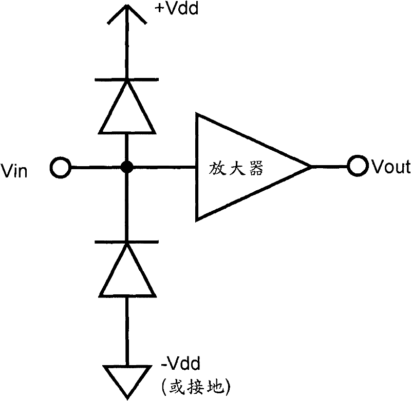
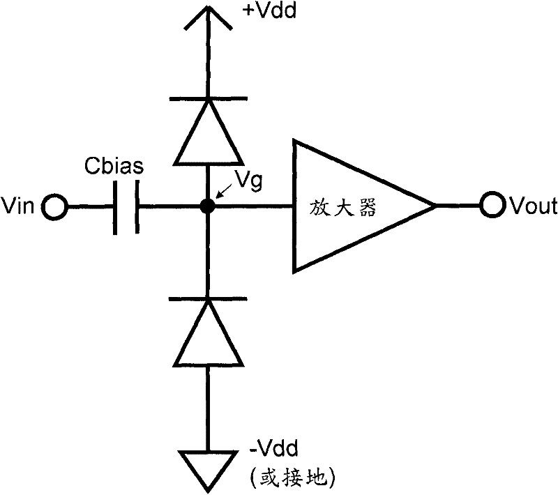
However, the PN diode will still produce a small capacitance, and the circuit still cannot get a reliable capacitance value.

Method used


Image

  • Touch panel test equipment and detecting device thereof
  • Touch panel test equipment and detecting device thereof
  • Touch panel test equipment and detecting device thereof

Examples


Embodiment Construction

[0018] Embodiments of the present invention will be described in detail below.

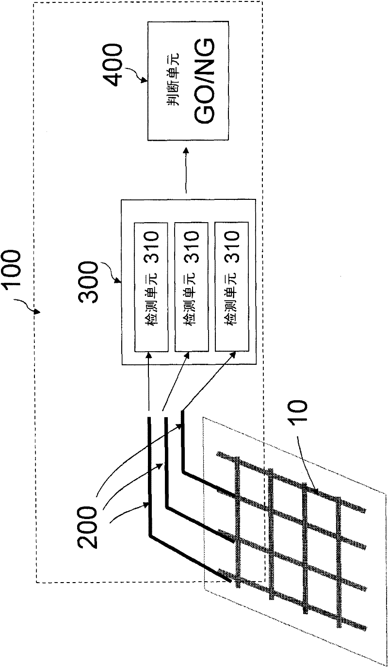
[0019] An embodiment of the present invention discloses a testing device 100 . image 3 A schematic diagram of a testing device 100 according to an embodiment of the present invention is shown. The testing device 100 includes a plurality of sensors 200 , a detection module 300 and a judgment module 400 .

[0020] The sensors 200 are used for sensing a plurality of tiny capacitive signals Vin of the object under test 10 (touch panel). It should be noted that in order to simplify the complexity of the description, the sensor 200 in the diagram is drawn with a simple line segment, and those skilled in the art should be able to understand it according to the diagram and description, and implement it using various sensors that are currently available or will be developed in the future . The detection module 300 receives and processes the plurality of tiny capacitance signals Vin to generate a plural...


PUM


Abstract

The invention provides touch panel test equipment and a detecting device thereof. The test equipment is used for testing the function of a touch panel; the test equipment and the detecting device thereof are used for detecting micro capacitance signals on the touch panel by using a special circuit; and the detecting device can be used for accurately sensing the micro capacitance signals and is not interfered by a peripheral circuit. The test equipment comprises a plurality of sensors, a detecting module and a judging module, wherein the detecting module is used for receiving and processing a plurality of micro capacitance signals to generate a plurality of output signals; the detecting module comprises a plurality of detecting units; and each detecting unit is coupled with a sensor and comprises an input node, a computing unit, at least one compensating unit and at least one electrostatic discharging protection unit.

Description

technical field [0001] The present invention relates to a testing device, especially a device for testing a touch panel, which uses a special circuit to detect tiny capacitance signals on the touch panel. Background technique [0002] Current touch technologies include resistive, capacitive, infrared, acoustic, optical, electromagnetic induction and digital. Among them, the resistive type has enjoyed the highest market share for a long time because of its simple structure and cost advantages, while the surface capacitive technology has incomparable advantages in durability and optics. Due to the high cost, its market share has always been lower than that of the resistive type. In recent years, because these patent restrictions have expired and can be used by the general public, and benefited from the progress of optical technology, it will bring new opportunities for the popularization of the capacitive type. [0003] Based on the above, the demand for testing capacitive to...

Claims


Application Information

Patent Timeline
IPC IPC(8): G06F3/044
Inventor 林韦丞杜文生倪瑞铭
Owner NAS TECH CORPS
Learn More