Supercharge Your Innovation With Domain-Expert AI Agents!

Power Factor Compensation Method

A technology of power factor and compensation method, which is applied in the direction of output power conversion device, light source, signal transmission system, etc., and can solve the problems that the power factor of electronic devices cannot be improved.

Inactive Publication Date: 2015-11-25
理察·蓝德立·葛瑞
View PDF5 Cites 0 Cited by
  • Summary
  • Abstract
  • Description
  • Claims
  • Application Information

AI Technical Summary

Problems solved by technology

[0005] Although there are many literatures pointing out that adding an active power factor correction circuit to the circuit can be used to improve the power factor, most of these power factor correction circuits can only play a good role in newly installed electronic devices alone, and cannot make other There are already installed electronic devices with poor power factor to obtain the effect of power factor improvement

Method used


Image

  • Power Factor Compensation Method
  • Power Factor Compensation Method
  • Power Factor Compensation Method

Examples


Embodiment Construction

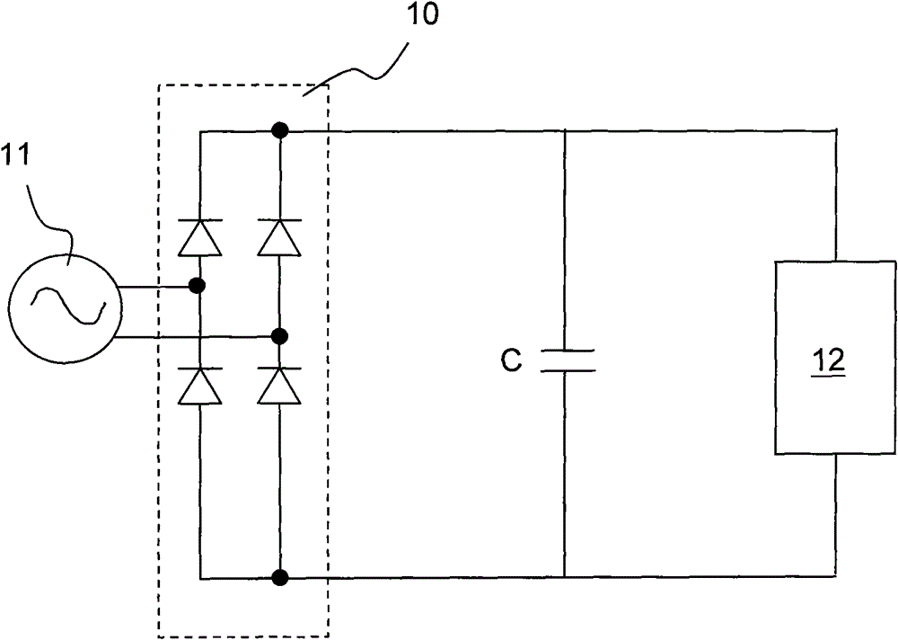
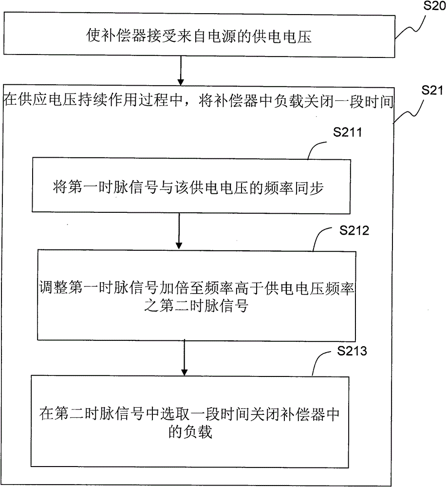
[0019] Please refer to FIG. 2 , which illustrates a flow chart of a power factor compensation method of an embodiment. The method of this embodiment can compensate the power factor of an electronic device connected to a common power supply with a compensator, wherein the electronic device is a Non-linear devices, compensation methods include:

[0020] Step S20: Make the compensator accept a supply voltage from the power supply; and

[0021] Step S21: Turn off a load in the compensator for a period of time while the supply voltage is continuously applied.

[0022] Step S21 further includes the following steps:

[0023] Step S211: synchronizing a first clock signal with the frequency of the supply voltage;

[0024] Step S212: adjusting the first clock signal to be multiplied (multiple) to a second clock signal whose frequency is higher than that of the power supply voltage, and the second clock signal is phase-locked to the power supply voltage waveform;

[0025] Step S213: S...


PUM


Abstract

An approach is provided for a power factor compensating method to compensate other electronic devices that use a common power source in order to improve power factor from the perspective of a power company. The other electronic device is a type of a non-linear load, and the method enables a compensator to receive a supply voltage from the power source commonly connected to the traditional electronic devices and disables a load of the compensator for a period. The period corresponds to a range that makes an overall supply current more proportional to the supply voltage.

Description

technical field [0001] The present invention is a power factor compensation method, especially a method of compensating and improving other low power factor electronic devices under a distribution network area (for example: home, office, building, factory, etc.) from the perspective of a power company method. Background technique [0002] Power factor (powerfactor) is a way to express whether the electrical or electronic load components have reached an ideal resistance state. If it is considered from the perspective of a power provider (such as a power company), when the power factor of a load is "1.0 ", the load can be regarded as an ideal resistance. In other words, when power is supplied to a load with a power factor of 1.0, the phases of the current and voltage will reach the same state. In practice, most electronic loads will have a Reactive components (reactive components) (such as: inductive or capacitive) that can reduce the power factor to below 1.0, these reactive...

Claims


Application Information

Patent Timeline
Patent Type & Authority Patents(China)
IPC IPC(8): H02M1/42
CPCH05B33/0809H05B41/295Y10T307/858H05B45/355
Inventor 理察·蓝德立·葛瑞蔡博名
Owner 理察·蓝德立·葛瑞
Features
  • R&D
  • Intellectual Property
  • Life Sciences
  • Materials
  • Tech Scout
  • Unparalleled Data Quality
  • Higher Quality Content
  • 60% Fewer Hallucinations
Learn More