LED (light emitting diode) illumination driving circuit and method

A technology of LED lighting and driving circuit, which is applied in the direction of lighting devices, lamp circuit layout, electric light source, etc. It can solve the problems of LED string damage, limit the number of single LED strings connected in series, and LED strings have different light emission, and achieve precise control. Effect

Active Publication Date: 2011-09-21
CHENGDU MONOLITHIC POWER SYST
View PDF4 Cites 30 Cited by
  • Summary
  • Abstract
  • Description
  • Claims
  • Application Information

AI Technical Summary

Problems solved by technology

However, the overvoltage protection will limit the number of series LEDs in a single string. If more LEDs are needed, they must be connected in parallel.
Due to the difference in the impedance of a single LED, there is an unequal current between different LED strings, which will cause the light emission of each LED string to be different, affect the backlight effect, and even cause damage to the LED string with a large current.

Method used


Image

  • LED (light emitting diode) illumination driving circuit and method
  • LED (light emitting diode) illumination driving circuit and method
  • LED (light emitting diode) illumination driving circuit and method

Examples


Embodiment Construction

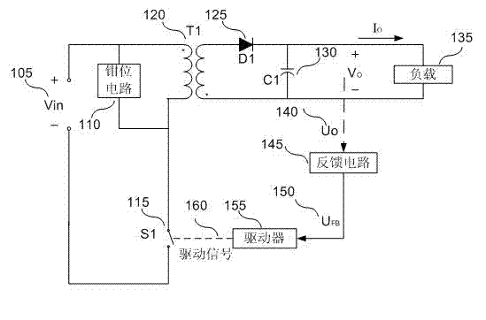
[0030] To illustrate, figure 1 One embodiment of a drive circuit according to the teachings of the present invention is shown. Input voltage 105 ( figure 1 Also shown as Vin) is connected to the energy transfer element 120 ( figure 1 Also shown as T1) and switch tube 115 ( figure 1 Also shown as S1 in ), the energy transfer element 120 is connected between the input end and the output end of the drive circuit, the energy transfer element 120 is described as a transformer with two coils, usually the transformer has more than two coils, Additional coils provide power to additional loads, provide offset voltages, or sense voltages across loads. The clamping circuit 110 is connected to the primary coil of the energy transfer element 120 to control the maximum voltage on the switch tube 115 . In one embodiment, the switch tube 115 is a transistor, such as a power metal oxide semiconductor field effect transistor (MOSFET).

[0031] When the switch tube 115 is running, the recti...


PUM


Abstract

The invention discloses an LED (light emitting diode) illumination driving circuit and a method. The LDE driving circuit comprises an energy transfer element, a switching tube, a driver and a feedback circuit, wherein the energy transfer component is used to receive and transfer electric energy; the switching tube is coupled with the energy transfer component and turns on or turns off based on the driving signal output by the driver; the driver is coupled with the feedback circuit and outputs the driving signal; the feedback circuit is coupled with the output end of the energy transfer component and outputs feedback signal to the driver; and the feedback circuit comprises a sampling circuit and a current sharing circuit. Therefore, the LED driving circuit has the advantages of over voltage protection and precise current sharing.

Description

technical field [0001] The invention relates to an LED drive circuit and method, in particular to a drive circuit and method for multiple LEDs in series and multiple LEDs in series and parallel. Background technique [0002] LED (Light Emitting Diode, LED for short) is a solid-state semiconductor device that can convert electrical energy into visible light. It can directly convert electricity into light. It has the advantages of easy control, low-voltage DC drive, and long service life. [0003] The application of LED can be mainly divided into three categories: LCD screen backlight, LED lighting, LED display. [0004] At present, most LCD TV / monitor screens and laptop LCD screens use CCFL fluorescent tubes as backlights. Due to the shortcomings of CCFL tubes such as relatively short lifespan and relatively unenvironmental protection, the backlights of the above-mentioned display screens are currently being used. LED backlight development. According to the size of the LC...

Claims


Application Information

Patent Timeline
Patent Type & Authority Applications(China)
IPC IPC(8): H05B37/02H05B44/00
CPCH05B33/0827H05B33/0812H05B33/0809Y02B20/341H05B45/395H05B45/46Y02B20/30H05B45/385
Inventor 胡进杜磊任远程张军明叶智俊
Owner CHENGDU MONOLITHIC POWER SYST
Why Eureka
Try Eureka