
Screwdriver of ratchet mechanism

A ratchet mechanism and screwdriver technology, applied to screwdrivers, manufacturing tools, etc., can solve problems such as difficult control of the direction, large size, complicated assembly and production steps, etc., and achieve the effect of loosening and loosening

Active Publication Date: 2015-05-06
孙 成纲
View PDF8 Cites 0 Cited by
  • Summary
  • Abstract
  • Description
  • Claims
  • Application Information

AI Technical Summary

Problems solved by technology

However, such a screwdriver is completely turned by manpower, which is laborious to use and the direction is not easy to control. It may cause gyrations during the turning process, making it even more inconvenient to use.
Therefore, there have been some ratchet screwdrivers that can realize unidirectional idling, such as the disclosed "hidden ratchet screwdriver" of Chinese patent CN2307658Y and "a combined ratchet screwdriver" disclosed by Chinese patent CN2900088Y, the disclosed combined ratchet screwdriver of CN2307658Y Including spring, connecting rod 33 and transmission rod 44 and the ratchet group consisting of positioning ratchet 41, leftward ratchet 42 and rightward ratchet 42, positioning lug 445 and other components, the combined ratchet screwdriver disclosed by CN2900088Y includes a connecting seat, a sleeve Barrel, brake block, arc-shaped sliding sleeve and other structures, although these two types of ratchet screwdrivers can realize the one-way idling of the screwdriver, but such screwdrivers have complex structures, large volumes, and complicated assembly and production steps. , it is easy to cause the screwdriver to be inflexible and malfunction due to damage or missing of a small part

Method used


Image

  • Screwdriver of ratchet mechanism
  • Screwdriver of ratchet mechanism
  • Screwdriver of ratchet mechanism

Examples


Embodiment Construction

[0017] The present invention will be further described in detail below in conjunction with the accompanying drawings and embodiments.

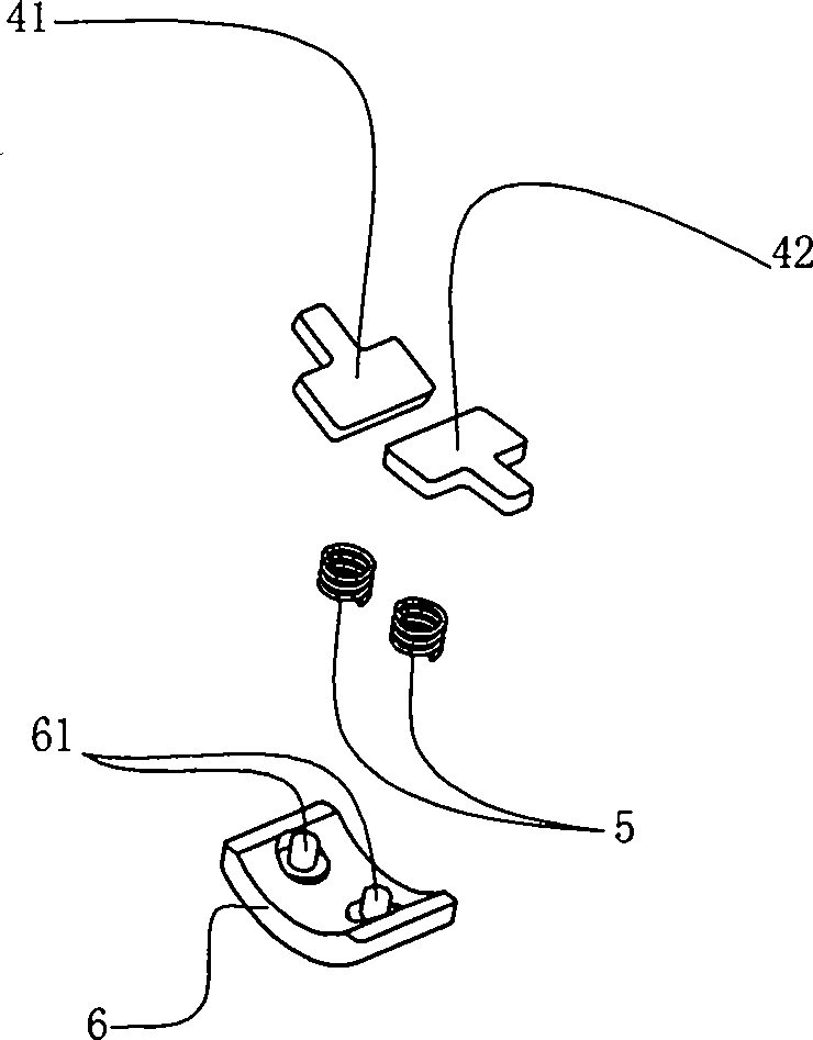
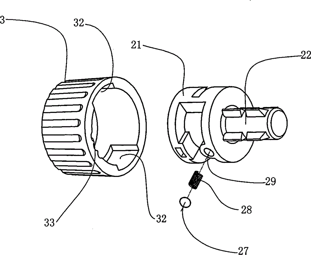
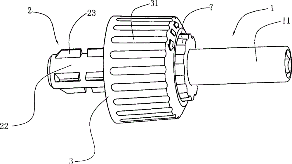
[0018] figure 1 It is a three-dimensional view of the screwdriver of the present invention. The screwdriver in this figure has been assembled, including the front rod 1 and the rear rod 2, as well as the rotating sleeve 3 on the rear rod 2 and the fixed sleeve 7 between the front rod 1 and the rear rod 2 . figure 2 It is a three-dimensional exploded view of the screwdriver of the present invention. As shown in the figure, the front rod 1 includes a cavity 11 at the front for fixedly connecting the screwdriver bit and a central gear 12 at the rear of the cavity 11. The cavity 11 It can be used to connect different types of screwdriver bits to tighten or loosen various types of screws. The rear rod 2 includes a connecting part 22 and a base part 21. The front end of the base part 21 has a thread 24, and the base part The diameter of 21 is lar...


PUM


Abstract

The invention discloses a screwdriver of a ratchet mechanism, comprising a front rod, a rear rod and a handle, wherein the front part of the front rod is connected with a cavity of a cutter head of the screwdriver and the rear part of the front rod is provided with a central gear piece; the front part of the rear rod is provided with a base part and the rear part of the rear rod is provided with a connection part; the central gear piece is inserted in the base part and fixedly connected with the base part and can rotate in the base part. The screwdriver is characterized by further comprising a left lock plate, a right lock plate and a middle control plate; a rotary sleeve head for controlling the rotation direction is sleeved outside the base part; under the matching of the rotary sleeve head, the central control plate and the lock plates, the functions of the rotation lock and the one-way rotation lock of the central gear piece can be realized and the one-way idle operation of the screwdriver is realized; the rotation direction of the screwdriver can be controlled more conveniently by users in the use process; and the screws can be screwed and unscrewed more conveniently in a labor-saving way.

Description

technical field [0001] The invention relates to a screwdriver, in particular to a screwdriver whose rotation direction can be controlled. Background technique [0002] As a commonly used hardware, a screwdriver is used for tightening screws. A common screwdriver, as shown in Chinese patent CN2071113U, usually includes a handle 1, a knife bar 2 and a knife head 3, and the user drives the knife bar 2 and the knife head by turning the handle 1 3 to rotate, so that the cutter head 3 drives the screw to rotate to tighten the screw. However, such a screwdriver is completely turned by manpower, and it is laborious to use and the direction is not easy to control. It may cause gyrations during the turning process to make it more inconvenient to use. Therefore, there have been some ratchet screwdrivers that can realize unidirectional idling, such as the disclosed "hidden ratchet screwdriver" of Chinese patent CN2307658Y and "a combined ratchet screwdriver" disclosed by Chinese patent...

Claims


Application Information

Patent Timeline
Patent Type & Authority Patents(China)
IPC IPC(8): B25B15/04
Inventor 孙成纲
Owner 孙 成纲
Learn More