Pressing switching waterway mechanism

A waterway and water inlet technology, applied in mechanical equipment, water supply devices, water supply mains, etc., can solve the problems of large switching force, large space occupation, inconvenient switching, etc. Effect

Active Publication Date: 2011-10-05
XIAMEN SOLEX HIGH TECH IND CO LTD
View PDF4 Cites 26 Cited by
  • Summary
  • Abstract
  • Description
  • Claims
  • Application Information

AI Technical Summary

Problems solved by technology

The existing rotary switching waterway mechanism has the following disadvantages: 1. The fan-shaped disc and the valve body are always close together, so the switching f

Method used


Image

  • Pressing switching waterway mechanism
  • Pressing switching waterway mechanism
  • Pressing switching waterway mechanism

Examples


Embodiment Construction

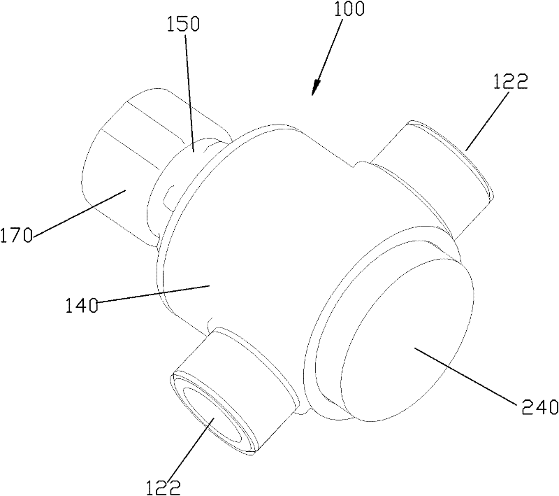
[0040] Please check Figure 1 to Figure 8 , press to switch the waterway mechanism, which includes a valve body 100 and a switching mechanism.

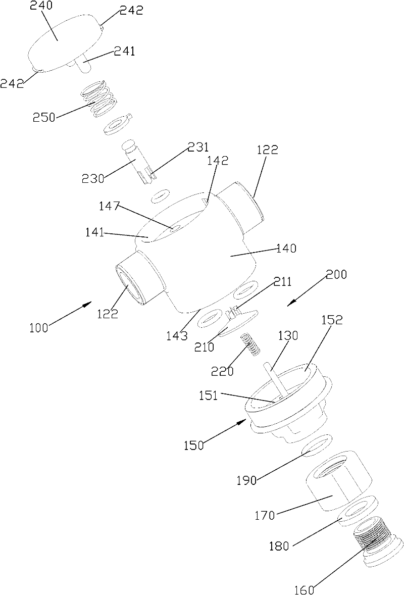
[0041] The valve body 100 includes a main body 140 , an upper cover 150 , a joint 160 , a joint nut 170 , a washer 180 and a sealing ring 190 .

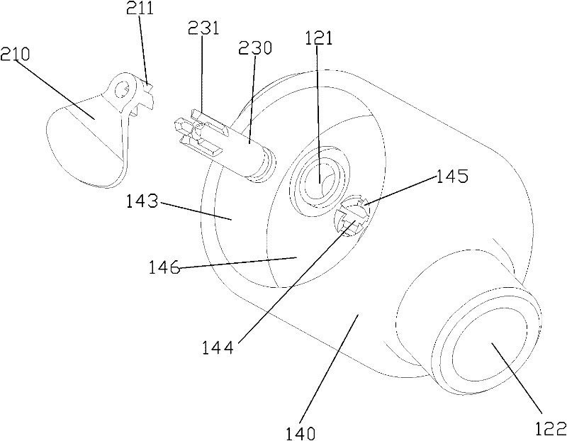
[0042] The top surface of the main body 140 is recessed to form a water outlet chamber 143 , and the bottom surface of the water outlet chamber 143 is a switching surface 146 . The upper cover 150 includes a top wall 151 and a peripheral wall 152 extending downward from a periphery of the top wall 151 . A guide shaft 130 is fixed at the center of the bottom surface of the bottom wall 151 . The peripheral wall 152 and the water outlet cavity 143 are sealed and fixed together, so that the main body 140 and the upper cover 150 are sealed and fixed together. The bottom surface of the main body 140 is recessed to form an assembly groove 141 , and an axial positioning groove 142 is provided on ...


PUM


Abstract

The invention discloses a pressing switching waterway mechanism, which comprises a valve body and a switching mechanism, wherein the valve body is provided with a water inlet route, a plurality of water outlet routes, a guiding shaft, a guiding slot and a third gear set; the switching mechanism comprises a fan-shaped plate, an offsetting spring and a pressing element; a first gear set is arrangedon the center of the circle of the fan-shaped plate; the first gear set is relatively sleeved outside of the guiding shaft in a sliding and rotating manner; the plurality of water outlet routes are switched by relatively rotating the fan-shaped plate and the valve body; the guiding slot is in sliding connection with the pressing element; a second gear set is arranged at the tail end of the pressing element; when the first gear set is matched with the second gear set and the third gear set, the pressing element slides forwards under the action of a pressing force; when the first gear set is matched with the second gear set, the fan-shaped plate slides and rotates forwards and the offsetting spring stores energy; and when the offsetting spring releases the energy and the first gear set is matched with the third gear set, the fan-shaped plate slides reversely and rotates forwards and the pressing element resets. The pressing switching waterway mechanism has the advantages that an automatic ball-point pen type mechanism is formed by the pressing element, the offsetting spring, the fan-shaped plate and the valve body, and the switching operation can be conveniently performed.

Description

technical field [0001] The invention relates to a press switching waterway mechanism. Background technique [0002] The switching waterway mechanism is mainly divided into a rotating switching waterway mechanism and a sliding switching waterway mechanism. The existing rotation switching waterway mechanism realizes switching mainly through the relative rotation between the fan-shaped disc and the valve body. A rotating cover is arranged outside the valve body, and a synchronous coaxial rotation connection relationship is formed between the cover and the fan-shaped disc. A protruding handle is provided on the cover, so that the cover can be rotated relative to the valve body by operating the protruding handle. , can drive the fan-shaped plate to rotate relative to the valve body, and can realize waterway switching. The existing rotary switching waterway mechanism has the following disadvantages: 1. The fan-shaped disc and the valve body are always close together, so the swit...

Claims


Application Information

Patent Timeline
IPC IPC(8): B05B1/16B05B12/02
CPCF16K11/074E03C1/023E03B7/075F16K11/02Y10T137/8778
Inventor 郭福利彭海松黄辉周华松
Owner XIAMEN SOLEX HIGH TECH IND CO LTD
Why Eureka
Try Eureka