Scroll fluid machine

A scroll compressor and fluid technology, applied in the field of scroll compressors, can solve the problems of reduced reliability, pressure rise, performance, reliability, etc., to improve performance and reliability, suppress pressure rise, and achieve high reliability. Effect

Inactive Publication Date: 2011-10-05
HITACHI JOHNSON CONTROLS AIR CONDITIONING INC
View PDF5 Cites 3 Cited by
  • Summary
  • Abstract
  • Description
  • Claims
  • Application Information

AI Technical Summary

Problems solved by technology

When liquid refrigerant flows in, there is a possibility that the reliability will be reduced due to the decrease of lubricity in the back pressure area or the bearing part, and the oil film rupture due to the foaming of the liquid refrigerant.
[0006] In addition, there is also such a problem that when the operation is stopped for a certain period of time under low temperature conditions, the refrigerant is dissolved in the oil in the compressor (consisting of a compression mechanism and an electric motor), and when the oil-to-oil refrigerant ratio is high, The oil is prone to the following phenomena: In the back pressure area, the oil with the refrigerant dissolved in it foams, resulting in an increase in the back pressure, an increase in the thrust force of the orbiting scroll, and the refrigerant gas generated by the foam (compressed (refrigerant with higher pressure of the refrigerant gas in the chamber) flows into the compression chamber, causing the pressure in the compression chamber to rise beyond expectation, resulting in a decrease in performance and reliability

Method used


Image

  • Scroll fluid machine
  • Scroll fluid machine
  • Scroll fluid machine

Examples


Embodiment Construction

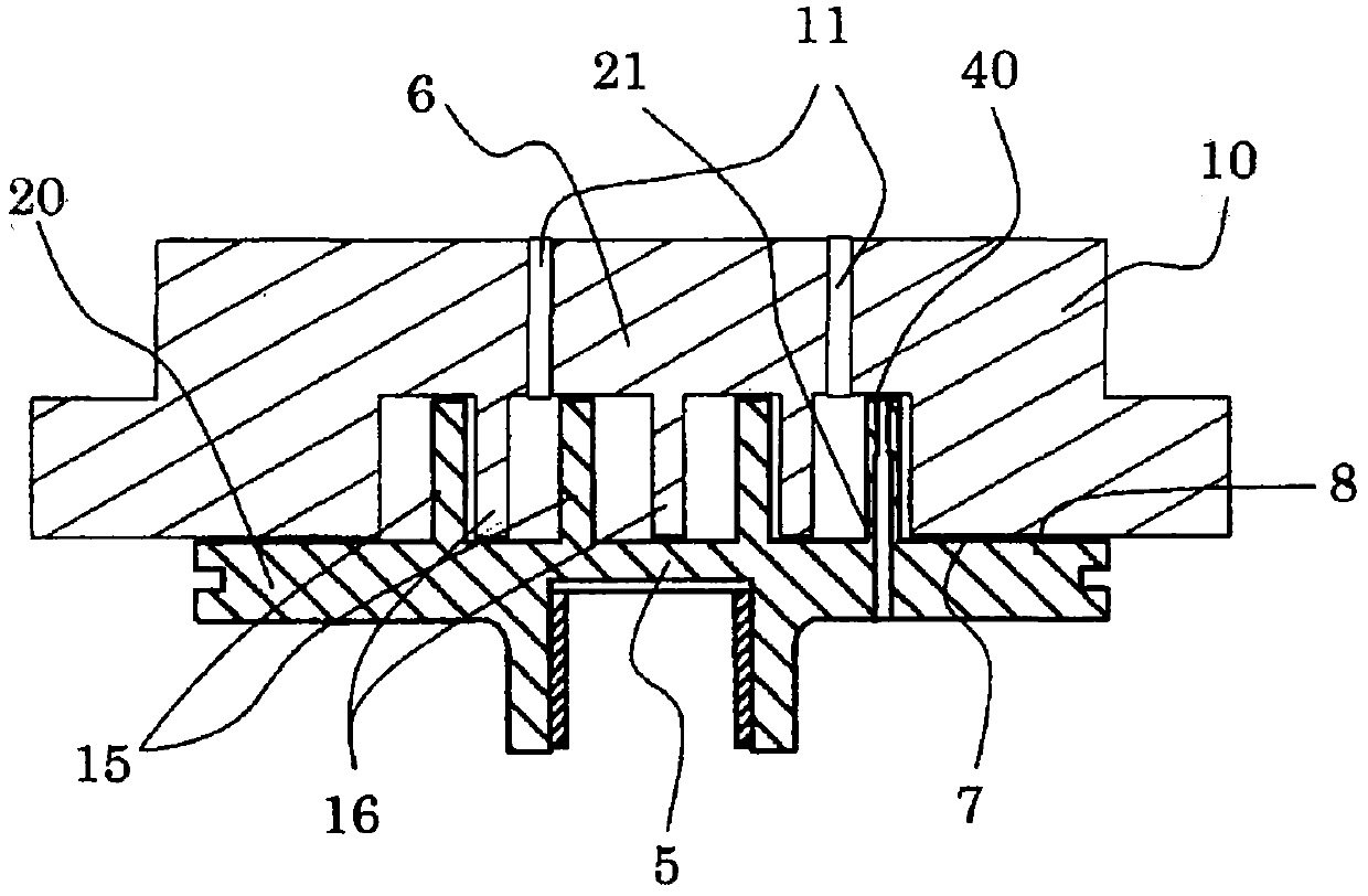
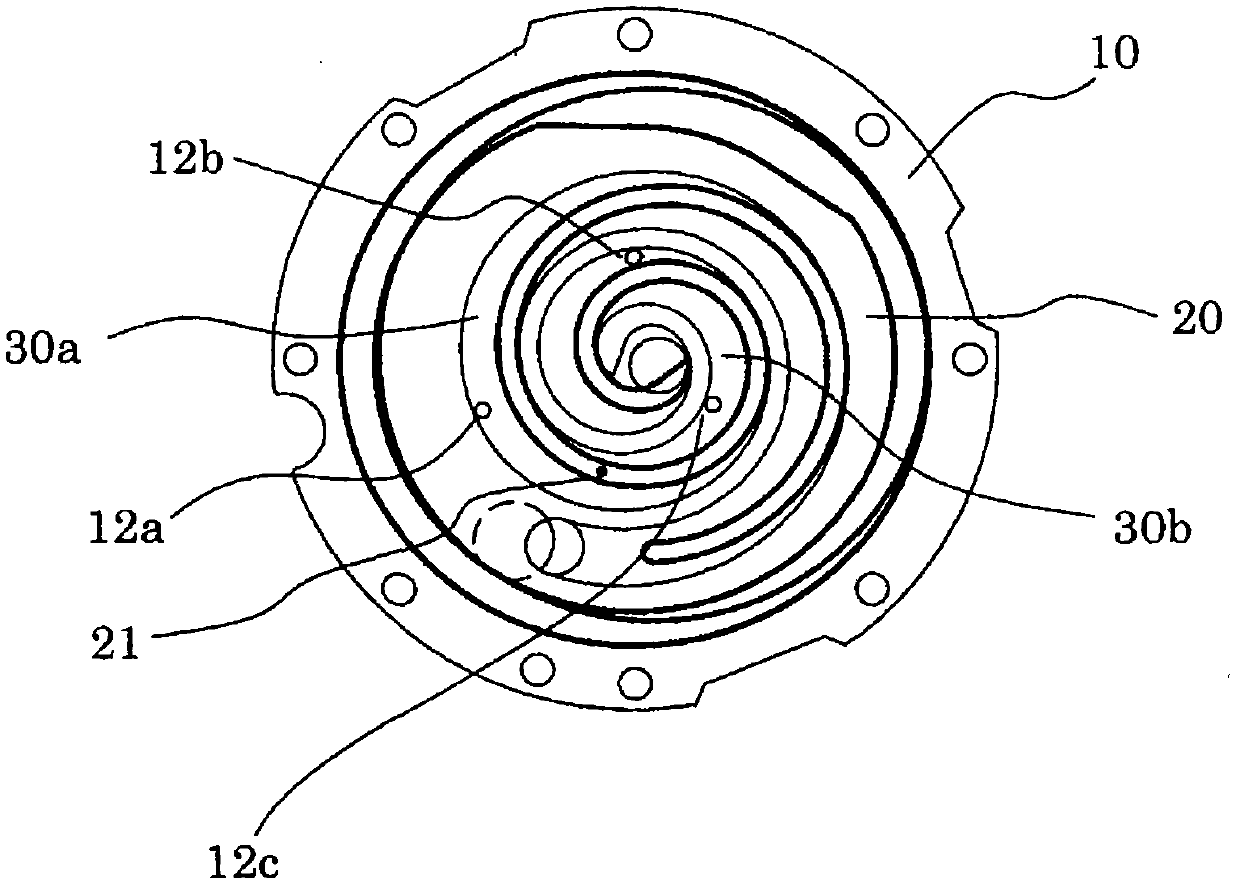
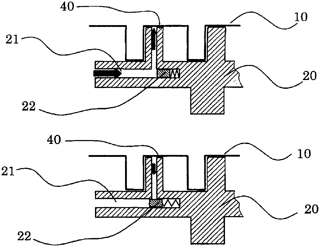
[0051] Below, refer to Figure 1 to Figure 5 , the scroll compressor according to the embodiment of the present invention will be described in detail. figure 1 is a cross section showing a compression chamber in a scroll compressor according to an embodiment of the present invention, that is, along figure 2 A cross-sectional view of line A-A'. figure 2 It is a figure which shows the schematic whole structure in the scroll compressor of this embodiment. image 3 It is a figure which shows an example of the resistance change of the communication flow path provided in the lap part of an orbiting scroll in the scroll compressor of this embodiment. Figure 4 It is a figure which shows another example of the resistance change of the communication flow path provided in the lap part of an orbiting scroll in the scroll compressor of this embodiment. Figure 5 It is a figure which shows still another example of the resistance change of the communication flow path provided in the la...


PUM


Abstract

To discharge high pressure liquid compressed when liquid refrigerant is sucked into a compression chamber to an outside without making the same enter into a back pressure area of a turning scroll or the like. A communication flow path 21 establishing communication between the compression chamber and the back pressure area of the turning scroll 20 is provided in a base plate and a lap of the turning scroll, and a relief mechanism 1 releasing predetermined pressure fluid in the compression chamber connecting to the communication flow path provided in the lap of the turning scroll 20 is provided in a fixed scroll 10. Consequently, entrance of liquid refrigerant into the back pressure area 31 is reduced while easily discharging liquid refrigerant at a time of pressure rise due to suction of liquid refrigerant to the compression chamber.; Also, if oil containing much refrigerant foams in the back pressure area 31 or the like, oil is discharged to the compression camber through the communication flow path 21 of the turning scroll 20 and is discharged from the relief mechanism 11 of the fixed scroll 10. Consequently, unexpected pressure rise in the back pressure area and the compression camber is reduced.

Description

technical field [0001] The invention relates to a fluid compressor and a fluid conveying machine used in refrigerating and air-conditioning devices, air compressors, etc., in particular to a scroll compressor. Background technique [0002] Conventionally, among scroll compressors suitable for indoor air conditioners, a scroll compressor having a structure in which a helical lap is formed on a bottom plate is known, for example, from Patent Document 1. The overlapping parts of the fixed scroll and the orbiting scroll engage each other relatively, and form a plurality of compression chambers, apply back pressure to the back of the orbiting scroll, and make the face plates (periphery of the bottom plate) of the two scrolls contact, In addition, an anti-rotation mechanism is installed on the back of the orbiting scroll so that the orbiting scroll does not rotate but performs orbital motion, thereby continuously reducing the volume of the compression chamber to compress the fluid...

Claims


Application Information

Patent Timeline
Patent Type & Authority Applications(China)
IPC IPC(8): F04C18/02
CPCF04C18/0215F04C29/0028F04C29/0035F04C29/028F04C2210/26F04C2240/40Y10S415/00Y10S417/00
Inventor 寺井利行大岛健一岛田昌浩
Owner HITACHI JOHNSON CONTROLS AIR CONDITIONING INC
Why Eureka
Try Eureka