Electromagnetic damping shock absorber

A technology of electromagnetic damping and shock absorber, applied in the direction of shock absorber, shock absorber, shock absorber-spring combination, etc. Reduced coercive force requirements, optimized damping coefficient, and better vibration reduction effect

Inactive Publication Date: 2011-10-05
SHANDONG UNIV OF TECH
View PDF6 Cites 25 Cited by
  • Summary
  • Abstract
  • Description
  • Claims
  • Application Information

AI Technical Summary

Problems solved by technology

In addition, the hydraulic shock absorber has limited damping force, and it is difficult to apply to high-frequency vibration, and the fluid is easy to leak
The traditional spring-type shock absorber uses its elastic recovery performance to achieve vibration reduction. Because the spring vibration reduction is prone to excitation and fatigue, the high-frequency vibration-reduction performance is poor, and noise is generated during work. The spring-type shock absorber is not suitable for modern society. development requirements
In recent years, a variety of permanent magnet shock absorbers have appeared, but the permanent magnets are required to have a high coercive force to avoid demagnetization, and the magnetic flux leakage is also large, and at the same time, they cannot adapt to the vibration reduction of the vibrating body with changing vibration parameters.

Method used


Image

  • Electromagnetic damping shock absorber
  • Electromagnetic damping shock absorber
  • Electromagnetic damping shock absorber

Examples


Embodiment Construction

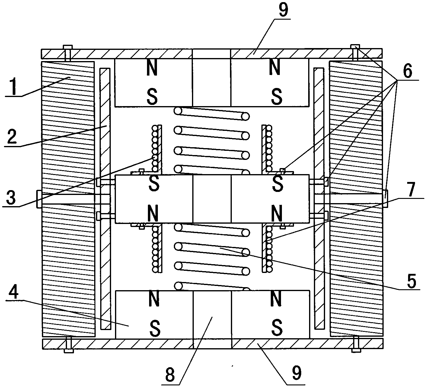
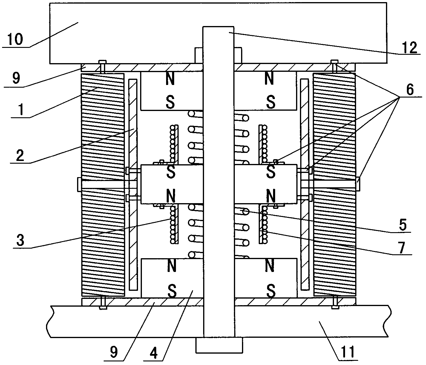
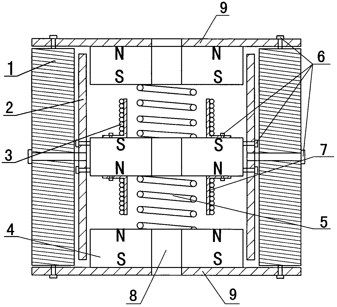
[0015] exist Figure 1-2 In the shown embodiment: rubber shock absorber 1 with openings at both ends, metal antimagnetic round tube 2 fitted and fixed in rubber shock absorber 1, and metal antimagnetic round tube 2 placed in the metal antimagnetic round tube 2 from top to bottom Three permanent magnets 4 and the spring 5 that are press-fitted between the permanent magnets 4, wherein the two open ends of the rubber shock absorber 1 are fixed with an end cover 9, and the two ends of the metal antimagnetic circle have a certain gap from the end cover 9; The adjacent ends of the adjacent permanent magnets 4 have the same magnetism, and the permanent magnet 4 in the middle is fixedly connected with the metal anti-magnetic round pipe 2 through the bolt 6. The upper and lower end faces of the permanent magnet 4 are fixed with a coil support 7, and the closed The induction coil 3 is wound on the coil support 7, and neither the coil support 7 nor the induction coil 3 touches the adjace...


PUM


Abstract

The invention provides an electromagnetic damping shock absorber which is characterized by comprising a rubber shock damping cylinder, a metal diamagnetic circular tube, three permanent magnets and springs, wherein the metal diamagnetic circular tube is sleeved and fixed in the rubber damping cylinder; the three permanent magnets are placed in the metal diamagnetic circular tube from top to down with intervals; the springs are pressed among the permanent magnets; an end cover is fixed at two ends of the rubber damping cylinder; certain clearances are arranged between the two ends of the metal diamagnetic circular tube and the end covers; the magnetism properties of the adjacent ends of adjacent permanent magnets are the same; the permanent magnet positioned in the middle is fixedly connected with the metal diamagnetic circular tube through a bolt; coil supports are fixed on an upper end surface and a lower end surface of the permanent magnet; enclosed induction coils are wound on the coil supports; the coil supports and the induction coils are all not contact with the adjacent permanent magnets; the center of each end cover and the center of each permanent magnet are all provided with penetrated bolt holes; and the bolt holes, the springs and the coil supports are coaxial. The shock absorber has the advantages that the shock absorber has favorable damping properties, can convert mechanical energy into electric energy to utilize, and has adjustable resistance, the energy can be recycled, and the controllability is good and the like.

Description

technical field [0001] The invention relates to an electromagnetic damping shock absorber, which belongs to the technical field of shock absorbers. Background technique [0002] In order to improve the ride comfort of the car, the shock absorber is installed in parallel with the elastic element in the suspension to attenuate the vibration. Most of the shock absorbers used in the car suspension system are hydraulic shock absorbers. Shock absorbers and elastic elements undertake the task of buffering shocks and damping vibrations. If the damping force is too large, the elasticity of the suspension will deteriorate, and even the connecting parts of the shock absorber will be damaged. The shock absorber is a vulnerable part during the use of the car. The performance of the shock absorber will directly affect the driving stability of the car and the life of other parts. Therefore, we should keep the shock absorber in good working condition. In addition, the hydraulic shock absor...

Claims


Application Information

Patent Timeline
Patent Type & Authority Applications(China)
IPC IPC(8): F16F13/04
Inventor 柴山刚宪约张玉增牛恩拂
Owner SHANDONG UNIV OF TECH
Why Eureka
Try Eureka