Rotary motion and reciprocating motion converting device
What is AI technical title?
AI technical title is built by Patsnap AI team. It summarizes the technical point description of the patent document.
A conversion device and reciprocating motion technology, applied in the direction of transmission device, friction transmission device, belt/chain/gear, etc., can solve the problems of reducing the working efficiency of the piston, increasing the resistance of starting and shifting, accelerating the wear of the cylinder wall, etc., to achieve power Reasonable conversion of transmission and motion mode, improvement of conversion efficiency, and effect of increasing tangential force
Inactive Publication Date: 2014-07-23
安里千
View PDF5 Cites 0 Cited by
Summary
Abstract
Description
Claims
Application Information
AI Technical Summary
This helps you quickly interpret patents by identifying the three key elements:
Problems solved by technology
Method used
Benefits of technology
Problems solved by technology
[0005] 2. The swing of the connecting rod in the crankshaft-connecting rod mechanism causes the gas pressure acting on the piston to generate a lateral pressure acting vertically on the cylinder wall, which increases the lateral friction between the piston and the cylinder wall and accelerates the wear of the cylinder wall , which not only reduces the working efficiency of the piston, but also causes the "cylinder" to make the piston unable to work
[0006] 3. Since the top and bottom dead centers of the crankshaft correspond to the top and bottom dead centers of the piston, and the rotation diameter of the crankshaft is equal to the stroke of the piston, an energy storage flywheel needs to be installed so that the crankshaft crosses the top dead center and then ignites. The gas compression ratio in the cylinder is not at the maximum state at the moment of ignition. , reduce the gas explosion expansion pressure at the moment of ignition, and at the same time increase the resistance of starting and shifting due to the existence of the flywheel
Method used
Image
Click on the blue label to locate the original text in one second.
Reading with bidirectional positioning of images and text.
Examples
Embodiment Construction
[0042] Specific embodiments of the present invention will be described in detail below with reference to the accompanying drawings.
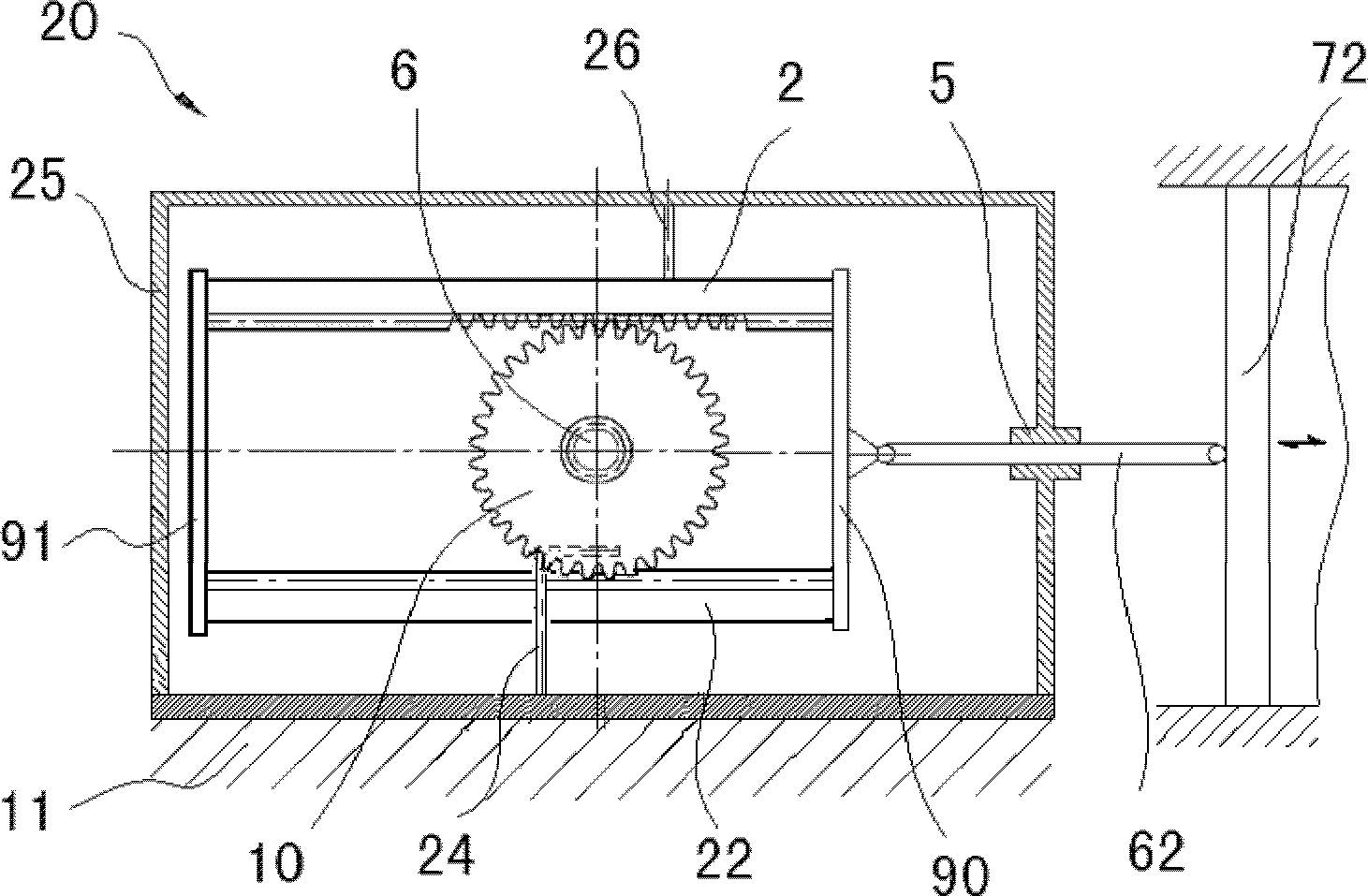
[0043] like Figures 1 to 4 shown, wherein a first embodiment provided by the present invention is depicted. exist figure 1 A rotary motion and reciprocating motion conversion device 20 provided by the present invention is depicted in FIG. 2 , which includes a piston 72 , one end of the piston rod 62 is connected with the piston 72 , and the housing 25 is mounted on the base 11 . The piston rod 62 is connected to the connecting plate 90 through the end wall of the housing 25 . The connecting plate 90 is connected to the ends of the first rack 2 and the second rack 22 , which are located above and below the transmission shaft 6 , respectively.
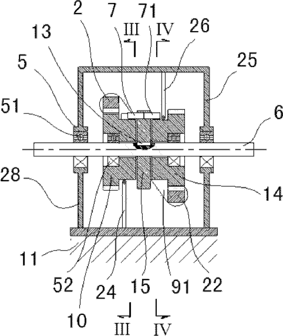
[0044] like figure 2 As shown, a bearing seat 5 is provided on the side wall 28 of the housing 25 , the drive shaft 6 is mounted in the bearing seat 5 , and the drive shaft 6 is mounted in the bearin...
PUM
Abstract
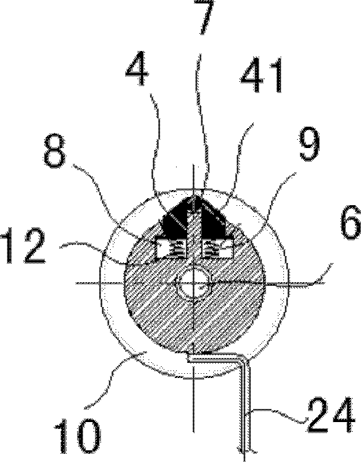
The invention relates to a rotary motion and reciprocating motion converting device (20) which comprises pistons (72, 74, 76, 78), wherein one end of each piston rods (62, 64) is connected with the pistons (72, 74, 76, 78); a shell (25) is installed on a base seat (11); a side wall (28) of the shell (25) is provided with a bearing seat (5); a transmission shaft (6) is installed in the bearing seat (5); the transmission shaft (6) is provided with transmission wheels (15, 17); a first gear (10) and a second gear (14) which can rotate relative to the transmission shaft (6) are installed close to the transmission wheels (15, 17); the first gear (10) and a first rack (2) are meshed mutually; the second gear (14) and a second rack (22) are meshed mutually; the first rack (2) and the second rack (22) are respectively positioned at two sides of the transmission shaft (6); connecting plates (90, 91) are connected with the end parts of the first rack (2) and the second rack (22); the connecting plates (90, 91) are connected with other ends of the piston rods (62, 64); the edge parts of the transmission wheels (15, 17) are provided with column pins (7, 71) extending out axially; a tooth-free parts of the first gear (10) and the second gear (14) are respectively provided with pin grooves (9, 21); the pin grooves (9, 21) are internally provided with sliding blocks (3, 4, 31, 32, 42) which are matched with the column pins (7, 71); and the restoration springs (12, 121) are arranged below the sliding blocks (3, 4, 31, 32, 42). Thus the conversion between the rotary motion and the reciprocating motion is realized.
Description
technical field [0001] The invention relates to a rotary motion and reciprocating motion conversion device, in particular to a rotary and linear reciprocating motion conversion device in which a rack and a gear mesh and a sliding block and a cylindrical pin are matched and driven alternately. Background technique [0002] At present, in the prior art, piston engines, compressors and other machines that need to convert between linear reciprocating motion and rotary motion generally use a crank connecting rod mechanism to realize motion conversion. [0003] The design and manufacture of the traditional crank connecting rod mechanism has been very perfect, but there are obvious shortcomings in both theoretical analysis and practical application: [0004] 1. The conversion efficiency of the crank connecting rod mechanism is low. Taking the piston-connecting rod-crankshaft (shank) mechanism engine as an example, the gas explosion pressure of the piston is transmitted to the cran...
Claims
Application Information
Patent Timeline
Application Date:The date an application was filed.
Publication Date:The date a patent or application was officially published.
First Publication Date:The earliest publication date of a patent with the same application number.
Issue Date:Publication date of the patent grant document.
PCT Entry Date:The Entry date of PCT National Phase.
Estimated Expiry Date:The statutory expiry date of a patent right according to the Patent Law, and it is the longest term of protection that the patent right can achieve without the termination of the patent right due to other reasons(Term extension factor has been taken into account ).
Invalid Date:Actual expiry date is based on effective date or publication date of legal transaction data of invalid patent.

